
Protective probe tip, particularly for use on a fiber-optic probe used in an endoscopic application

a protective and endoscope technology, applied in the field of probe tips, can solve the problems of not being able to use optical based imaging systems in the design, unable to maintain sterility during the application of the endoscope, etc., and achieve the effects of facilitating abutment, providing stability, and facilitating abutment to the tissu

Inactive Publication Date: 2008-01-24
ONCOSCOPE INC
View PDF89 Cites 19 Cited by
  • Summary
  • Abstract
  • Description
  • Claims
  • Application Information

AI Technical Summary

Benefits of technology

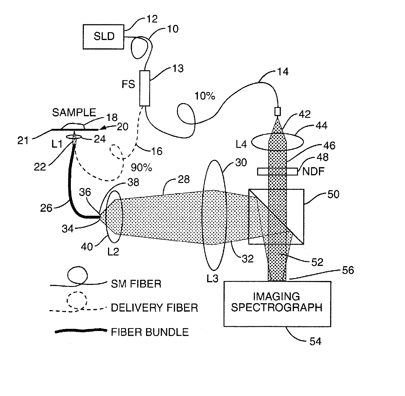
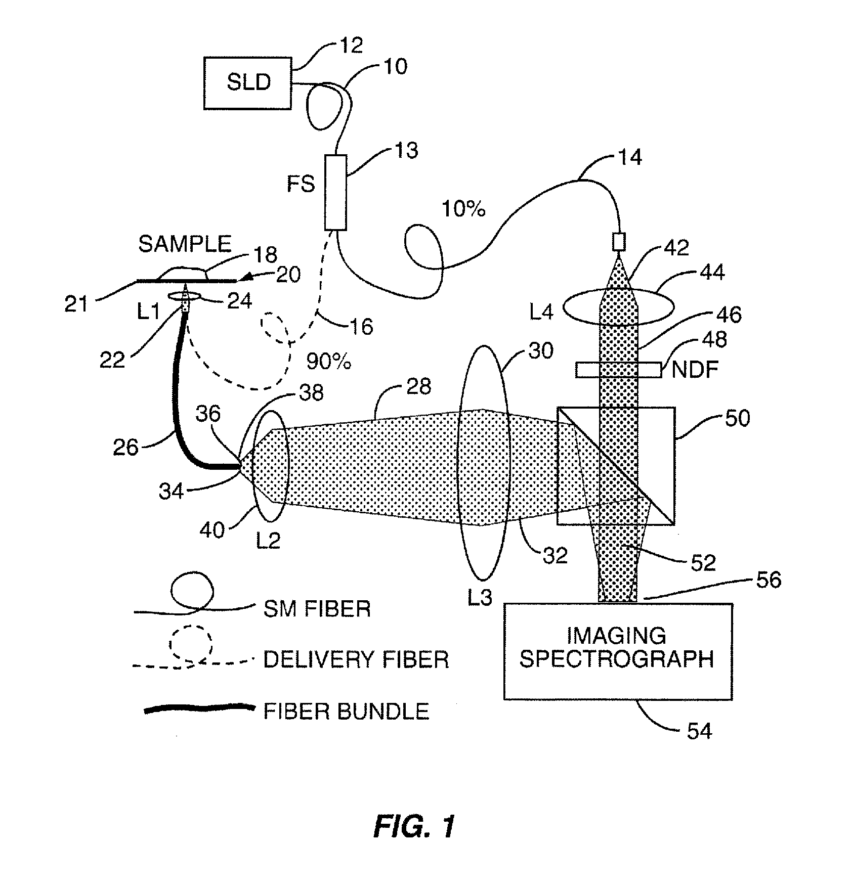
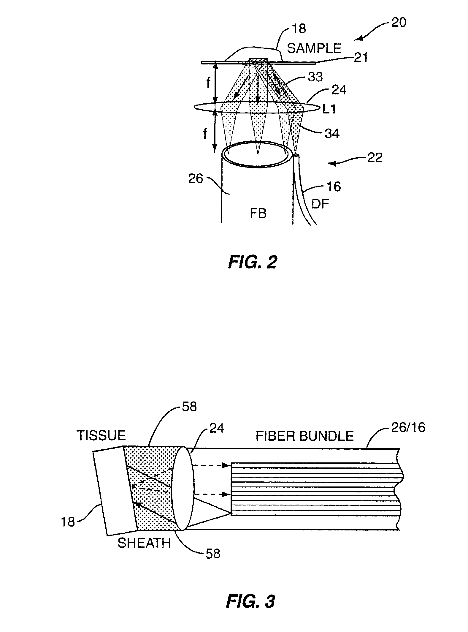
[0013] The fiber probe tip also employs an optical window on its distal end that is positioned relative to the imaging element. The optical window allows the reflected light from the tissue sample to pass through to the imaging element within the fiber probe tip. The optical window is located approximately one focal length away from the imaging element in one embodiment. This is so the reflected, scattered light from the tissue is properly captured when the fiber probe tip and its optical window are abutted to the tissue of interest. In the case of an angled-resolved LCI technique in the Fourier domain (fa / LCI) system, the fiber probe tip allows the maintenance of the tissue to be located approximately one focal length away from the imaging element so that the reflected, angular distribution of the reflected light is properly captured.
[0014] The fiber probe tip may employ different distal end designs to allow the fiber probe tip, and more particularly its optical window, to properly abut against the tissue of interest. The optical window should abut against the tissue of interest in order for the imaging element of the fiber probe tip to be located the proper distance away from the tissue of interest. The distal end of the fiber probe may be straight or angled to facilitate abutment to the tissue of interest. A suction device may also be employed on the distal end of the fiber probe tip to facilitate abutment to the tissue and provide stability. A separate channel path may be provided in the fiber probe tip to be used as a wash of the tissue and / or to provide vacuum assistance to assist in suction of the suction device to the tissue.
[0015] Designs are also provided to allow the fiber probe tip to either be fixed onto the fiber probe or removable. If removable, this allows the fiber probe tip to be disposed of after each endoscopic application to prevent washing and / or provide greater sterility. The design may include a locking system to lock the fiber probe tip in place during application. The fiber probe tip is then unlocked after use to then be disposed. If the locking system employs a channel in the sheath of the fiber probe tip, the fiber probe may be accessible from outside the fiber probe tip. Thus, a protective skirt may also be employed on the fiber probe tip. The skirt provides a method of covering the channel to prevent access to the fiber probe within the fiber probe tip and extending therefrom. The skirt can be designed to be retracted or coiled initially to allow the fiber probe tip to be easily and unobstructively attached to the fiber probe. The skirt can then be deployed after the fiber probe tip is attached and before endoscopic application begins.

Problems solved by technology

Both these patents include a provision for a channel through the protective sheath, which provides a point of access and thus may preclude maintenance of sterility during application of the endoscope.
These designs specifically call for the probe to abut the protector and do not maintain a fixed distance between the probe tip and tissue sample.
Thus, these designs may not be used with optical based imaging systems, including but not limited to a fa / LCI system.

Method used


Image

  • Protective probe tip, particularly for use on a fiber-optic probe used in an endoscopic application
  • Protective probe tip, particularly for use on a fiber-optic probe used in an endoscopic application
  • Protective probe tip, particularly for use on a fiber-optic probe used in an endoscopic application

Examples


Embodiment Construction

[0011] In embodiments of the present invention, a new probe tip is provided to facilitate clinical application of advanced optical spectroscopic techniques when using a fiber probe or bundle while maintaining sterility. The probe tip may be used in fiber-optic probe applications. While basic optical spectroscopic techniques can be applied with a variety of configurations, newly developed advanced methods, such as the angled-resolved LCI technique in the Fourier domain (fa / LCI) system for example, require precise location of the tissue under examination relative to the optical fiber and associated imaging elements.

[0012] In embodiments of the invention, the fiber probe tip includes a protective sheath over the optical fiber or bundle. The probe tip provides a sterile interface between the optical fiber and the tissue surface under examination during endoscopic applications. Because the fiber tip probe may be employed in optical spectroscopic techniques, the fiber probe tip includes ...


PUM


Abstract

A fiber probe tip, particularly for use on a fiber-optic probe in endoscopic applications. The probe tip prevents contamination of the probe imaging elements and maintains proper distal relationships between imaging components and tissue under examination. In one embodiment, the fiber probe tip is comprised of a sheath placed over an optical fiber. The probe tip provides a sterile interface between the optical fiber and the tissue. The fiber tip probe includes an imaging element to capture reflected light from the tissue. The fiber probe tip maintains the positioning of the imaging element relative to the optical fiber to properly capture reflected light from the tissue. The fiber probe tip may also contain an optical window positioned relative to the imaging element. The optical window allows the reflected light from the tissue to pass through to the imaging element and provide an optimized focal distance between the tissue and the imaging element for the imaging technology employed.

Description

RELATED APPLICATION [0001] This application claims priority to Provisional Application Ser. No. 60 / 807,985, entitled “Disposable, Sterile Probe Tip for Fiber Optic Probes,” filed on Jul. 21, 2006, and incorporated herein by reference in its entirety.FIELD OF THE INVENTION [0002] Embodiments of the present invention relate to a probe tip for protection of a probe, including a fiber-optic probe, used in endoscope applications. The probe tip may be disposable to maintain sterility. The probe tip may also allow distance maintenance of an imaging element in the probe with respect to examined tissue to ensure the proper capture of reflected light. The probe tip may be used on a fiber-optic probe used in low coherence interferometry (LCI) endoscope applications in particular. BACKGROUND OF THE INVENTION [0003] Examining tissue surfaces and / or structural features of cells in tissue is essential for many clinical and laboratory studies. For example, an endoscope is a type of probe that can b...

Claims


Application Information

Patent Timeline
IPC IPC(8): A61B1/00
CPCA61B1/00096A61B1/00142A61B1/00135A61B1/00101
Inventor WAX, ADAM
Owner ONCOSCOPE INC
Learn More