Camera control

Inactive Publication Date: 2008-01-31
ACCELERATED PICTURES
View PDF95 Cites 13 Cited by
  • Summary
  • Abstract
  • Description
  • Claims
  • Application Information

AI Technical Summary

Benefits of technology

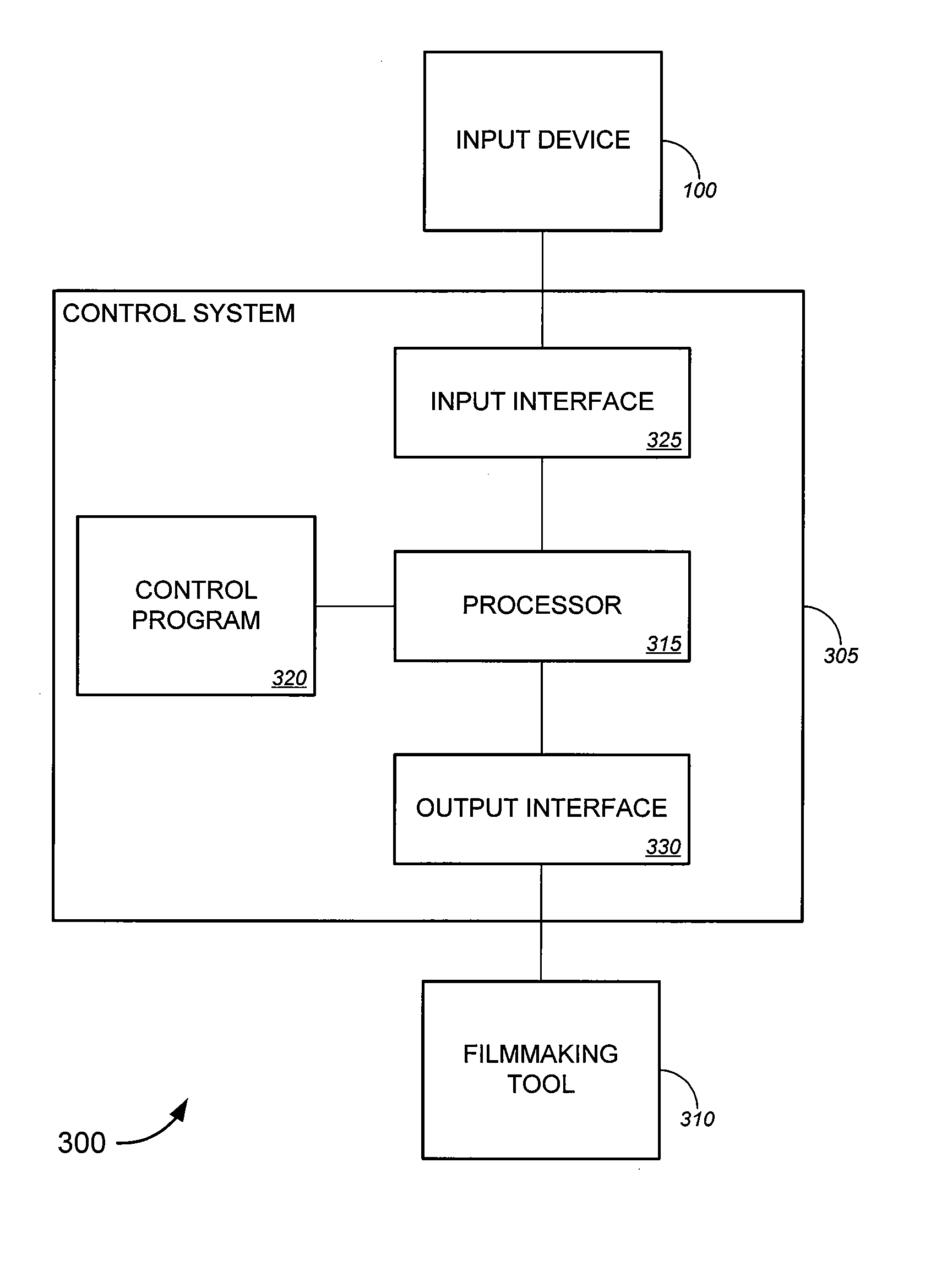
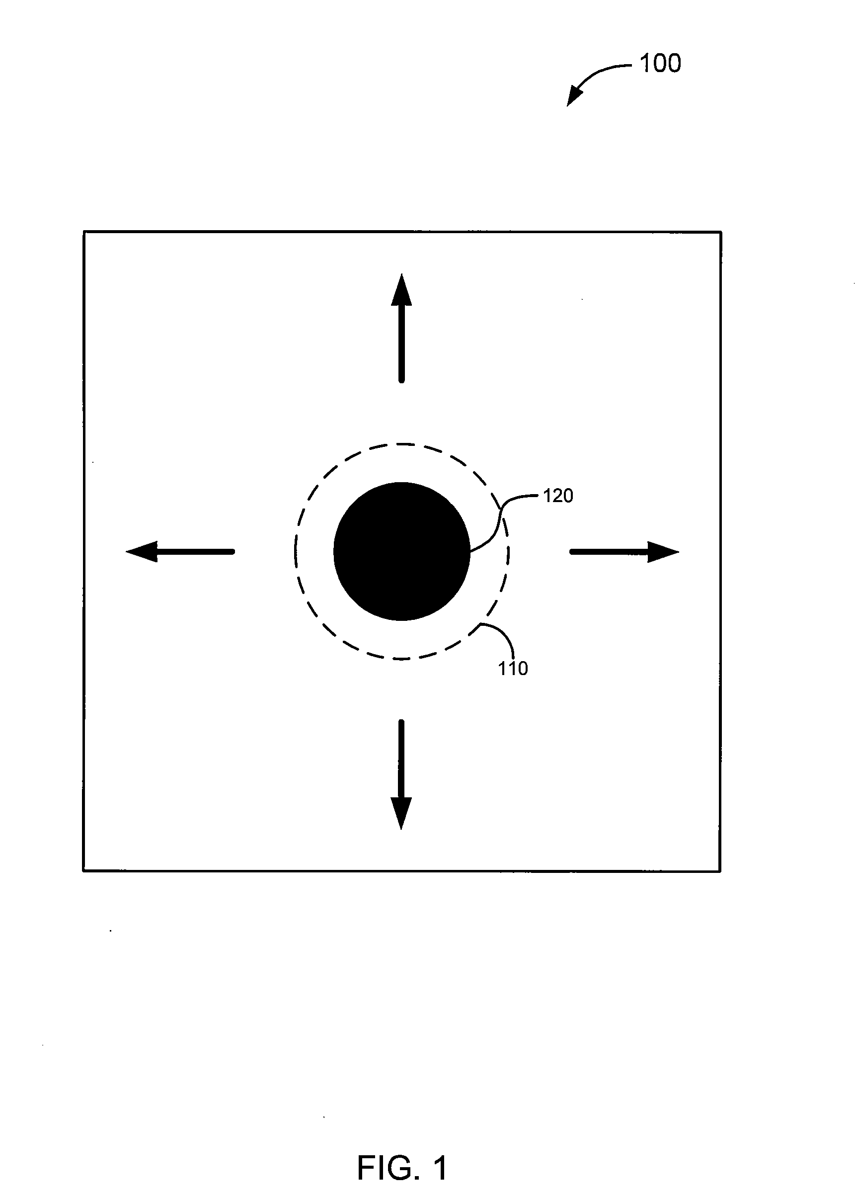
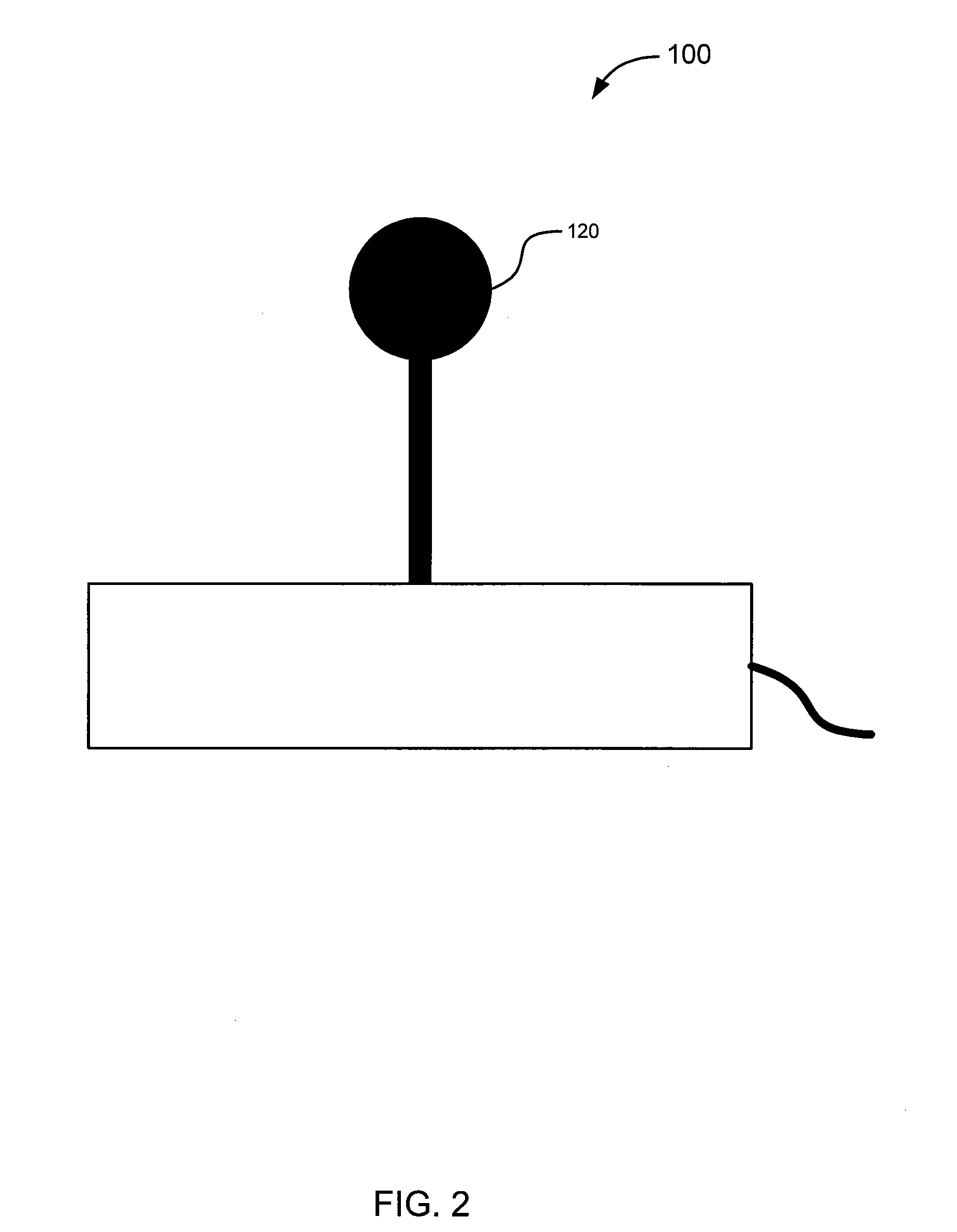
[0015] Embodiments of the invention provide tools for controlling cameras (as well as other objects), using an input device such as a joystick or game pad (to name but two examples). In one aspect, some embodiments establish a threshold, above which the input from the input device is fed directly to the object being controlled, and below which the input signal is processed to provide smoother operation. Beneficially, this feature provides a user (such as a camera operator, animator, etc.) with the ability have direct control over the (real or virtual) movem

Problems solved by technology

Typically, in control systems in which the speed of the camera motion is controlled by an input device such as a joystick, dynamic range issues prevent or significantly complicate the task of creating a smooth transition to a stationary state, particularly if the transition or “ease out” is to occur over a period of several seconds.
While it is possible to adjust the sensitivity curve of the controls (as discussed, for example, in U.S. patent application Ser. No. 11/261,441, already incorporated by reference) in order to expand the low-velocity region of the of the control system without sacrificing dynamic range and high velocity control, doing so generally results in a control system which is less satisfactory for general usage due to the changed sensitivity profile of the device.
In particular, the sensitivity changes can raise the difficulty of causing the camera to start moving—from a st

Method used


Image

  • Camera control
  • Camera control
  • Camera control

Examples


Embodiment Construction

[0036] While various aspects of embodiments of the invention have been summarized above, the following detailed description illustrates exemplary embodiments in further detail to enable one of skill in the art to practice the invention. In the following description, for the purposes of explanation, numerous specific details are set forth in order to provide a thorough understanding of the present invention. It will be apparent, however, to one skilled in the art that the present invention may be practiced without some of these specific details. In other instances, well-known structures and devices are shown in block diagram form. Several embodiments of the invention are described below, and while various features are ascribed to different embodiments, it should be appreciated that the features described with respect to one embodiment may be incorporated with another embodiments as well. By the same token, however, no single feature or features of any described embodiment should be c...


PUM


Abstract

Tools for controlling cameras (and other objects), using an input device. Some such tools may establish a threshold, above which the input from the input device is fed directly to the object being controlled, and below which the input signal is processed to provide smoother operation. This can allow for direct control over a camera (or other object) in large movements but still allow for smooth, controlled movements when slower movement is desired.

Description

CROSS-REFERENCE TO RELATED APPLICATIONS [0001] The present disclosure may be related to the following commonly assigned applications / patents (referred to herein as the “Related Applications”): [0002] This application claims priority from co-pending provisional U.S. patent application No. 60 / 834,216 filed Jul. 28, 2006 by Alvarez, et al. and entitled “Improved Camera Control,” which is hereby incorporated by reference, as if set forth in full in this document, for all purposes. [0003] This application is related to U.S. patent application Ser. No. 11 / 262,492, filed Oct. 28, 2005 by Alvarez et al. and entitled “Client / Server-Based Animation Software, Systems and Methods,” which is hereby incorporated by reference, as if set forth in full in this document, for all purposes. [0004] This application is also related to U.S. patent application Ser. No. 11 / 261,441, filed Oct. 28, 2005 by Alvarez et al. and entitled “Camera and Animation Controller, Systems and Methods,” which is hereby inco...

Claims


Application Information

Patent Timeline
IPC IPC(8): H04N5/232G09G5/00
CPCH04N5/232H04N23/66
Inventor ALVAREZ, DONALDPARRY, MARK
Owner ACCELERATED PICTURES
Why Eureka
Try Eureka