Imaging apparatus

a technology of imaging apparatus and reflected flash, which is applied in the field of imaging apparatus, can solve the problems of large difference in exposure time between the first reading line and the last reading line, difficult to allow the same reflected flash to fall on the entire light receiving surface of the image sensor, and difficult to accurately calculate the amount of main flash

Inactive Publication Date: 2008-01-31
CANON KK
View PDF5 Cites 22 Cited by
  • Summary
  • Abstract
  • Description
  • Claims
  • Application Information

AI Technical Summary

Benefits of technology

[0014]The present invention is directed to an imaging apparatus capable of accurately calculating an amount of main flash of a flash unit.
[0016]According to another aspect of the present invention, a method for controlling an imaging apparatus having an image sensor configured to image an object to generate image data includes controlling a main flash, to be performed by a flash unit configured to emit flash to an object, according to preliminary image data generated by the image sensor in association with a pre-flash performed by the flash unit, adjusting starting timings of exposures performed at a plurality of lines of the image sensor to a same timing when the pre-flash is performed, and shielding the image sensor from light before the preliminary image data is read from the image sensor.

Problems solved by technology

Consequently, it is difficult to allow the same reflected flash to fall on the entire light receiving surface of the image sensor.
Thus, there is a large difference in exposure time between the first reading line and the last reading line.
However, in a case where the electronic shutter speed is high, there is no overlapping timing with which a pre-flash is performed so that the exposure times respectively corresponding to the reading lines of the image sensor overlap.
Thus, there is a large difference in exposure time between the first reading line and the last reading line.
Consequently, the former method has a drawback in that a resolution obtained during a pre-flash is low.
Consequently, the latter method also has a drawback in that a resolution obtained during a pre-flash is low.
Accordingly, in the conventional imaging apparatuses, in a case where the electronic shutter speed is equal to or higher than a predetermined value, it is difficult to accurately calculate an amount of main flash of a flash unit.

Method used


Image

  • Imaging apparatus
  • Imaging apparatus
  • Imaging apparatus

Examples


Embodiment Construction

[0024]Various exemplary embodiments, features, and aspects of the invention will be described in detail below with reference to the drawings.

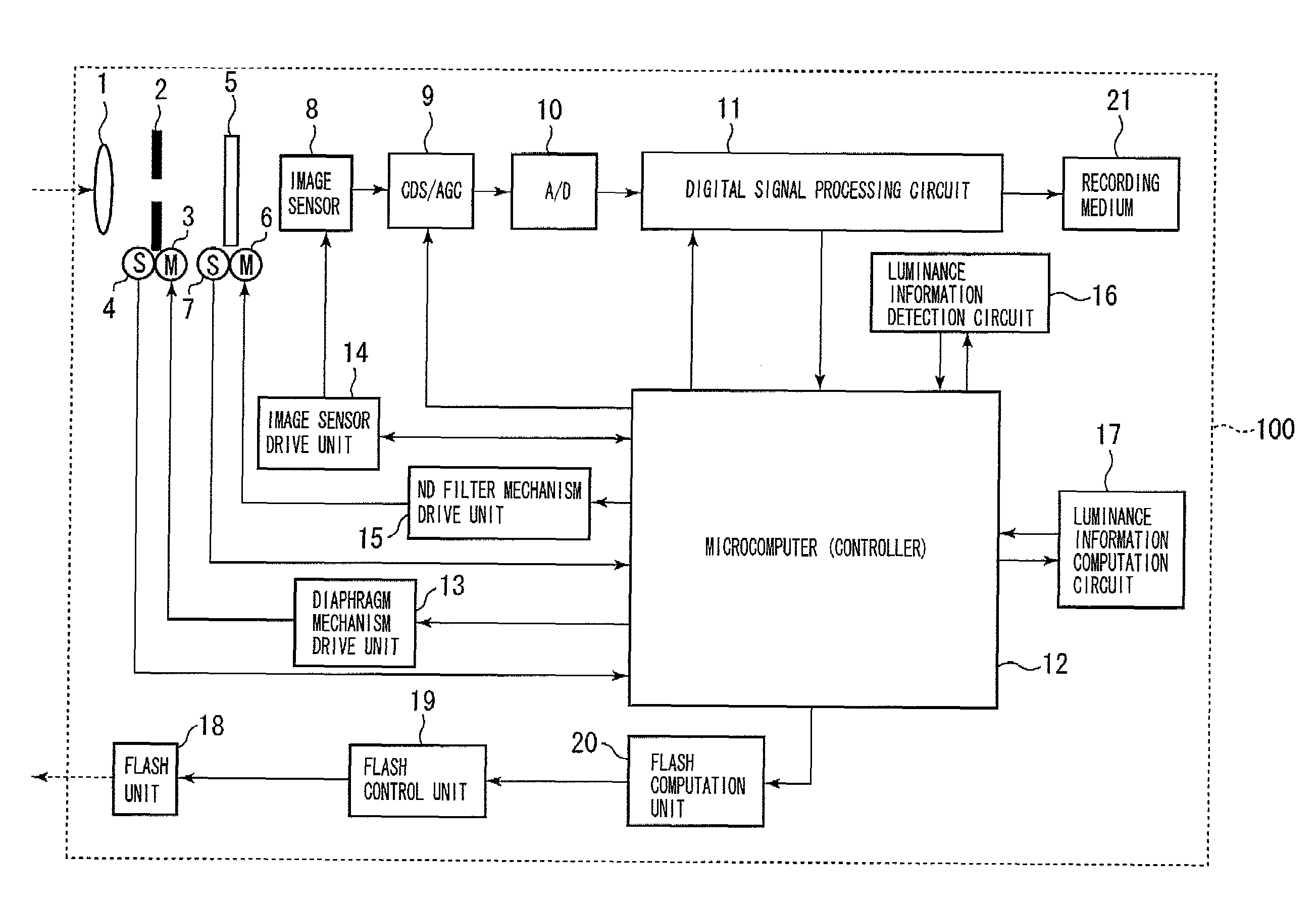
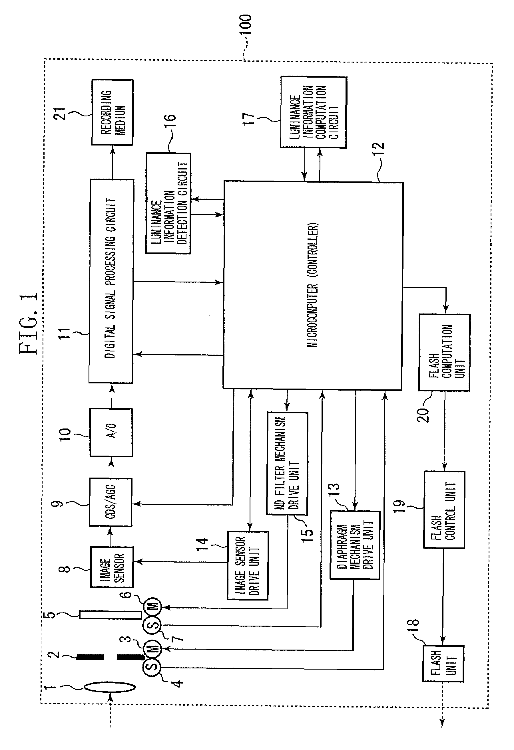
[0025]FIG. 1 illustrates a configuration of an imaging apparatus 100 according to an exemplary embodiment of the present invention. As illustrated in FIG. 1, a lens 1 introduces incident light into the imaging apparatus 100 from an outside thereof. For simplicity of drawing, only a single lens 1 is illustrated in FIG. 1. A diaphragm 2 adjusts an amount of incident light. A diaphragm drive motor 3 drives the diaphragm 2. A diaphragm state detection circuit 4 detects a driven state of the diaphragm 2.

[0026]The imaging apparatus 100 further includes a neutral density (ND) filter 5, an ND filter drive motor 6 configured to drive the ND filter 5, and an ND filter drive detection circuit 7 configured to detect a driven state of the ND filter 5. Incidentally, although the description of the present exemplary embodiment discusses the imaging apparatus ...


PUM


Abstract

An imaging apparatus includes an image sensor configured to image an object to generate image data, a flash control unit configured to control a main flash, to be performed by a flash unit configured to emit flash to an object, according to preliminary image data generated by the image sensor in association with a pre-flash performed by the flash unit, a first drive unit configured to adjust starting timings of exposures performed at a plurality of lines of the image sensor to a same timing when the pre-flash is performed, and a second drive unit configured to shield the image sensor from light before the preliminary image data is read from the image sensor.

Description

BACKGROUND OF THE INVENTION[0001]1. Field of the Invention[0002]The present invention relates to an imaging apparatus configured to control an operation of a flash emitting unit which emits flash to an object, and also relates to a control method therefor.[0003]2. Description of the Related Art[0004]There have been conventional imaging apparatuses configured to perform a flash control method for calculating an amount of main flash of a flash unit by performing, just before the main flash, a pre-flash to determine the amount of main flash.[0005]In an imaging apparatus employing an image sensor, such as a complementary metal-oxide semiconductor (CMOS) sensor, of XY address type having pixels arranged in a two-dimensional matrix array on a light receiving surface, starting timings of exposure times respectively corresponding to reading lines of the image sensor vary with the reading lines. Consequently, it is difficult to allow the same reflected flash to fall on the entire light recei...

Claims


Application Information

Patent Timeline
Patent Type & Authority Applications(United States)
IPC IPC(8): H04N5/222H04N25/00H04N101/00
CPCH04N5/2354H04N23/74
Inventor MAEDA, MUNEYOSHI
Owner CANON KK
Why Eureka
Try Eureka