Sound Image Localization Control Apparatus

a control apparatus and sound image technology, applied in the direction of electrical transducers, stereophonic arrangments, transducer details, etc., can solve the problem of difficult to improve the sense of sound image localization at different seats with substantially the same degr

Inactive Publication Date: 2008-01-31
PANASONIC INTELLECTUAL PROPERTY MANAGEMENT CO LTD
View PDF2 Cites 40 Cited by
  • Summary
  • Abstract
  • Description
  • Claims
  • Application Information

AI Technical Summary

Benefits of technology

[0029] As described above, according to the present invention, the audio signal to be input to the audio reproduction means is processed, such that an interaural amplitude level difference obtained when a reproduction sound provided by the audio reproduction means is listened to at a first listening position is equal to an interaural amplitude level difference obtained when the reproduction sound is listened to at a second listening position different from the first listening position. Thus, the same level of sound image localization effect is provided at a plurality of listening positions.

Problems solved by technology

With such a method, however, it is difficult to improve the sense of sound image localization at different seats with substantially the same degree.

Method used


Image

  • Sound Image Localization Control Apparatus
  • Sound Image Localization Control Apparatus
  • Sound Image Localization Control Apparatus

Examples


first embodiment

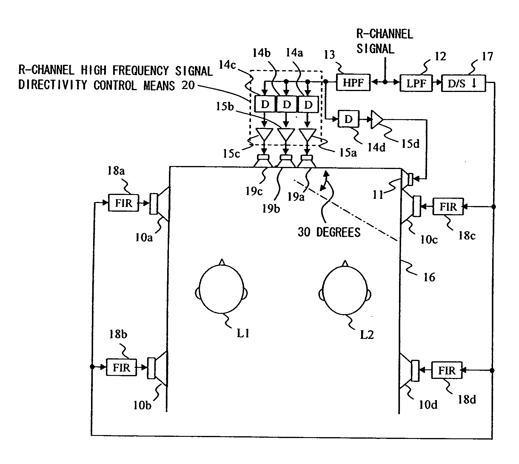
[0104]FIG. 7 shows a vehicle-mountable sound image localization control apparatus according to a first embodiment. The vehicle-mountable sound image localization control apparatus shown in FIG. 7 allows both the crew members L1 and L2 located in front seats of the vehicle 16 to perceive localization of a sound image of an R-channel signal of an audio signal in a desired direction over the entire frequency band. For a home-use audio system allowing listeners to enjoy music contents or the like including L and R sound sources, it is recommended to localize the L and R sound sources at 30 degrees on the left and 30 degrees on the right. By contrast, in a vehicle, it is preferred to localize the L and R sound sources at larger angles of about 60 degrees on the left and about 60 degrees on the right. The reason is that if the L and R sound sources are localized at 30 degrees on the left and 30 degrees on the right, the listeners feels suppressed due to the specific condition that the veh...

second embodiment

[0121]FIG. 18 shows a vehicle-mountable sound image localization control apparatus according to a second embodiment. The vehicle-mountable sound image localization control apparatus shown in FIG. 18 allows both the crew members L1 and L2 located in front seats of the vehicle 16 to perceive localization of a sound image of an R-channel signal of an audio signal in a desired direction over the entire frequency band. Specifically, in the following description, it is assumed that the vehicle-mountable sound image localization control apparatus is operated for the purpose of localizing an R sound source in the direction of 60 degrees on the right like the vehicle-mountable sound image localization control apparatus in the first embodiment.

[0122] In FIG. 18, reference numerals 11c through 11e represent speakers of a high frequency reproduction speaker array attached to a front door pillar; reference numerals 14a through 14f represent delay devices; reference numeral 15a through 15f repre...


PUM


Abstract

An audio signal high frequency component controlled in terms of directivity is reproduced, or an audio signal high frequency component compensated in terms of frequency characteristic or controlled in terms of directivity is reproduced, such that the reflected sound comes from a direction in which the high frequency component is intended to be localized. The sound pressure in a seat where a desired localization effect is not provided due to the arrangement of speakers is compensated such that the interaural amplitude level in the seat is equal to that of another seat. Thus, an equivalent level of localization effect is provided in a plurality of seats, especially for an audio signal high frequency component, without significantly increasing the number of the speakers.

Description

TECHNICAL FIELD [0001] The present invention relates to a sound image localization control apparatus. BACKGROUND ART [0002] Conventionally, when reproducing music, movie or other contents in a vehicle, the sense of sound image localization is improved by adjusting gain balance or time alignment through delay insertion among speakers. With such a method, however, it is difficult to improve the sense of sound image localization at different seats with substantially the same degree. In order to solve this problem, an apparatus for erasing crosstalk among a plurality of speakers is proposed. Hereinafter, an audio reproduction apparatus described in patent document 1 will be described with reference to the figures. [0003]FIG. 1 shows an audio reproduction apparatus described in patent document 1. In this figure, an audio reproduction apparatus 1 is applied to front seats of a vehicle. Specifically, two crew members L1 and L2 as listeners in the vehicle listen to a signal B1 reproduced by...

Claims


Application Information

Patent Timeline
Patent Type & Authority Applications(United States)
IPC IPC(8): H04R1/40H04R3/00H04S1/00
CPCH04S3/002
Inventor MIZUNO, KOKANO, HIROYUKI
Owner PANASONIC INTELLECTUAL PROPERTY MANAGEMENT CO LTD
Why Eureka
Try Eureka