Optical zoom tracking apparatus and method, and computer-readable recording medium for performing the optical zoom tracking method

a tracking apparatus and optical zoom technology, applied in the field of optical zoom lens system, can solve the problems of insufficient power for implementing optical zoom function, limited camera function, dim image occurrence, etc., and achieve the effect of effectively using a limited amount of power

Active Publication Date: 2008-01-31
LG ELECTRONICS INC
View PDF7 Cites 17 Cited by
  • Summary
  • Abstract
  • Description
  • Claims
  • Application Information

AI Technical Summary

Benefits of technology

[0014] Another object of the present invention is to provide an optical zoom tracking apparatus capable of providing an optical zoom function to effectively use a limited amount of power, a method for controlling the optical zoom tracking apparatus, and a computer-readable recording medium for performing the optical zoom tracking method.

Problems solved by technology

The most complicated design method of the optical zoom lens system may include at least 30 lens components and several mobile optical components as necessary.
However, the above-mentioned conventional art has a disadvantage in that an unexpected defocusing problem occurs during the zooming operation of the zoom lens, resulting in the occurrence of a dim image.
And, the above-mentioned conventional art is unable to sufficiently provide the power required for implementing the optical zoom function.
Therefore, in the case of a mobile phone equipped with the optical zoom lens system, a camera function is limited under the condition at least a predetermined amount of battery power has been consumed, the camera function may be limited, and the mobile phone may be compulsorily switched off during either the optical zoom tracking operation or the camera operation.

Method used


Image

  • Optical zoom tracking apparatus and method, and computer-readable recording medium for performing the optical zoom tracking method
  • Optical zoom tracking apparatus and method, and computer-readable recording medium for performing the optical zoom tracking method
  • Optical zoom tracking apparatus and method, and computer-readable recording medium for performing the optical zoom tracking method

Examples


Embodiment Construction

[0033] Reference will now be made in detail to the preferred embodiments of the present invention, examples of which are illustrated in the accompanying drawings. Wherever possible, the same reference numbers will be used throughout the drawings to refer to the same or like parts.

[0034] Prior to describing the present invention, it should be noted that a zoom lens is indicative of a variator lens capable of adjusting a magnifying power of a camera, and a focus lens is indicative of a master- or compensator-lens for compensating for a focus dimmed by the zooming operation of the camera.

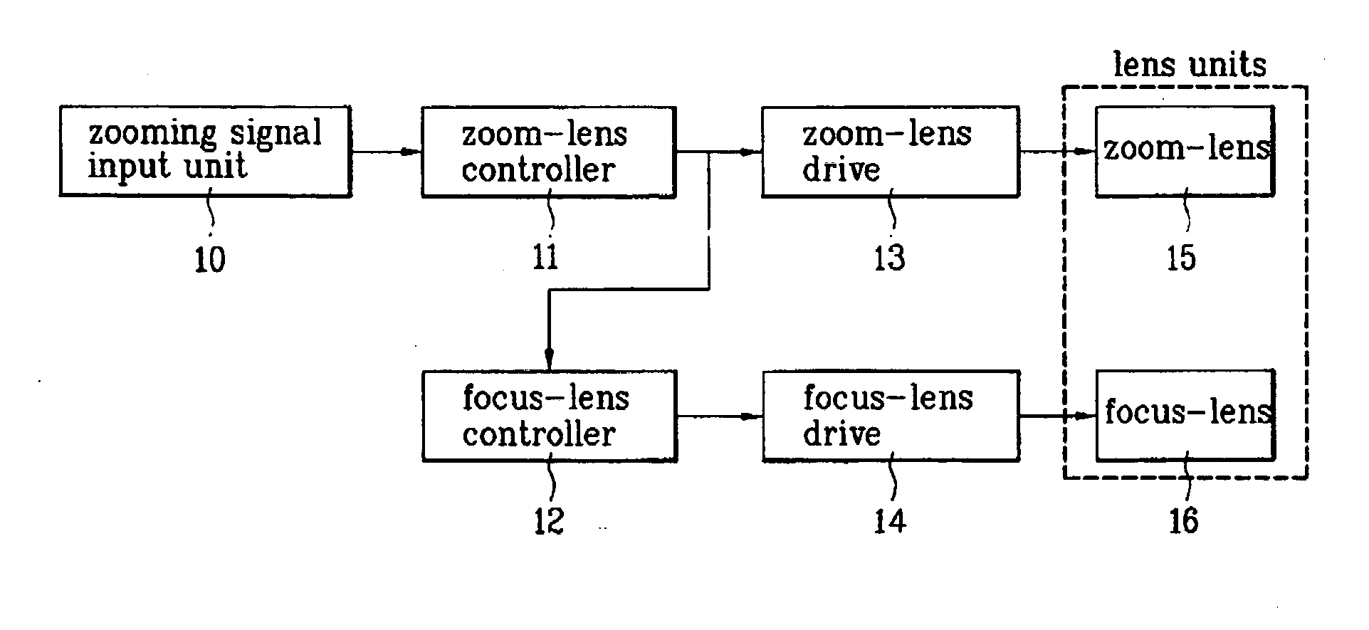
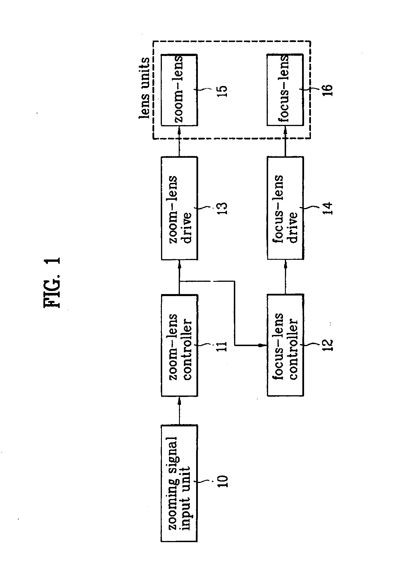
[0035]FIG. 1 is a block diagram illustrating an optical zoom tracking apparatus for a zoom camera module according to the present invention.

[0036] Referring to FIG. 1, a zoom camera module according to a preferred embodiment of the present invention includes a zooming-signal input unit 10, lens controllers 11 and 12, lens drivers 13 and 14, and lens units 15 and 16.

[0037] The optical zoom tracking ...


PUM


Abstract

An optical zoom tracking apparatus and method, and a computer-readable recording medium for performing the optical zoom tracking are disclosed. If an optical zoom function of a digital camera or mobile phone is executed, the optical zoom tracking apparatus commands a focus lens to move according to a continuous zooming operation, such that a clear image can be maintained while the image is continuously zoomed in or out, resulting in the effective use of limited power. The optical zoom tracking apparatus includes: a zoom lens which moves to adjust a magnification (i.e., a magnifying power) of a camera; a focus lens interoperable with the zoom lens; a zoom-lens drive for moving the zoom lens; a focus-lens drive for moving the focus lens; and a focus-lens controller for determining a moving distance of the focus lens according to a moving distance of the zoom lens, and transmitting a control signal corresponding to the moving distance of the focus lens to the focus-lens drive.

Description

[0001] This application claims the benefit of Korean Patent Application Nos. 10-2006-0014757, filed on Feb. 15, 2006, 10-2006-0114922, filed on Nov. 21, 2006, which is hereby incorporated by reference as if fully set forth herein. BACKGROUND OF THE INVENTION [0002] 1. Field of the Invention [0003] The present invention relates to an optical zoom lens system, and more particularly to an optical zoom tracking apparatus and method for use in the optical zoom lens system, and a computer-readable recording medium for performing the optical zoom tracking method. [0004] 2. Discussion of the Related Art [0005] The optical zoom lens system has been widely mounted to a digital camera or digital VCR. Recently, the optical zoom lens system can also be mounted to a mobile phone or a portable multimedia player (PMP), etc. The above-mentioned optical zoom lens system can be implemented according to a variety of design methods. The most complicated design method of the optical zoom lens system may ...

Claims


Application Information

Patent Timeline
Patent Type & Authority Applications(United States)
IPC IPC(8): G02B7/02G03B13/32G03B17/00
CPCG03B13/32G02B7/102
Inventor CHI, YONG SEOK
Owner LG ELECTRONICS INC
Why Eureka
Try Eureka