Torque Detecting Apparatus
a technology of torque detection and detecting equipment, which is applied in the direction of instruments, apparatus for force/torque/work measurement, transportation and packaging, etc., can solve the problem that the positioning will be carried out only with difficulty, and achieve the effect of less cost, high accuracy and much eas
- Summary
- Abstract
- Description
- Claims
- Application Information
AI Technical Summary
Benefits of technology
Problems solved by technology
Method used
Image


Examples
embodiment 1
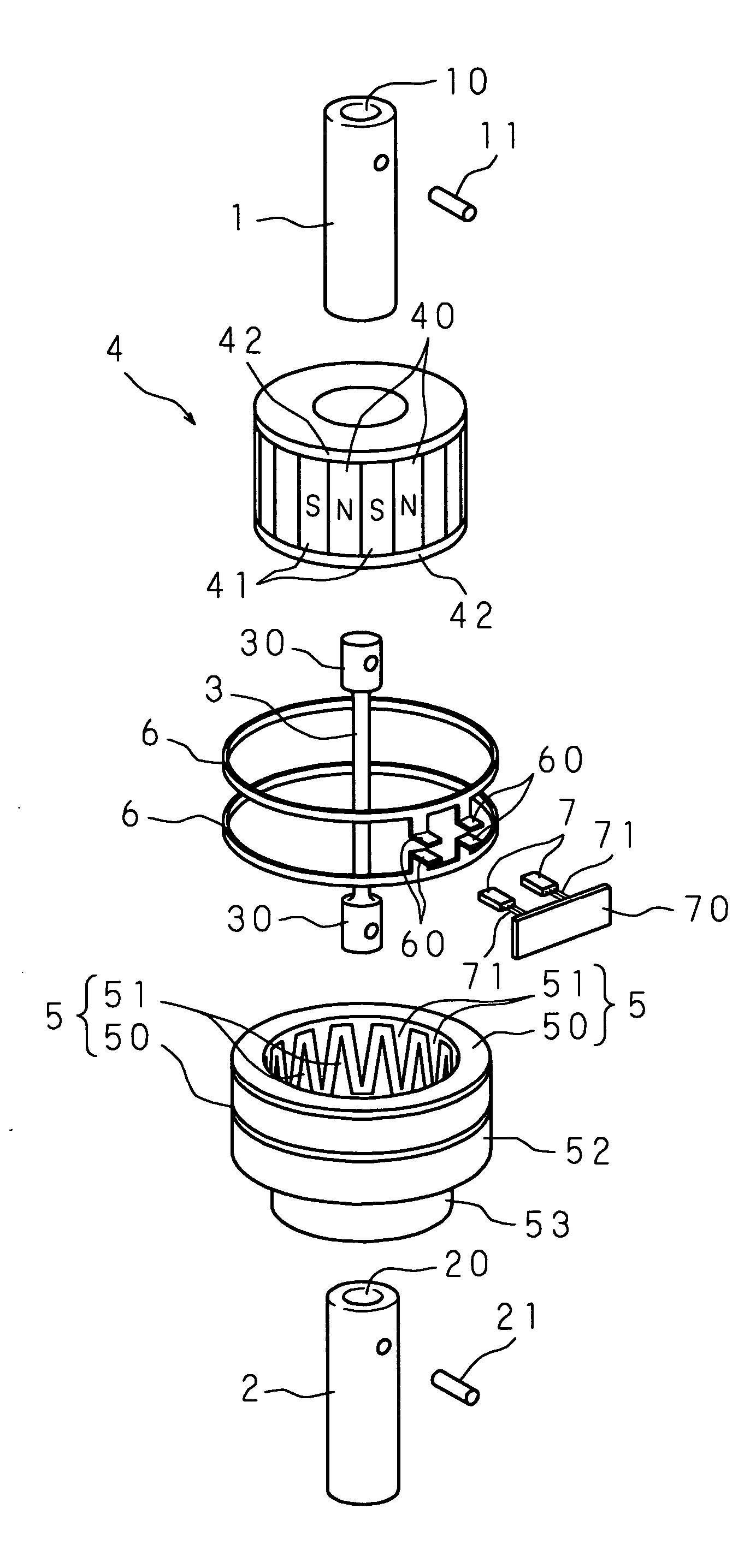
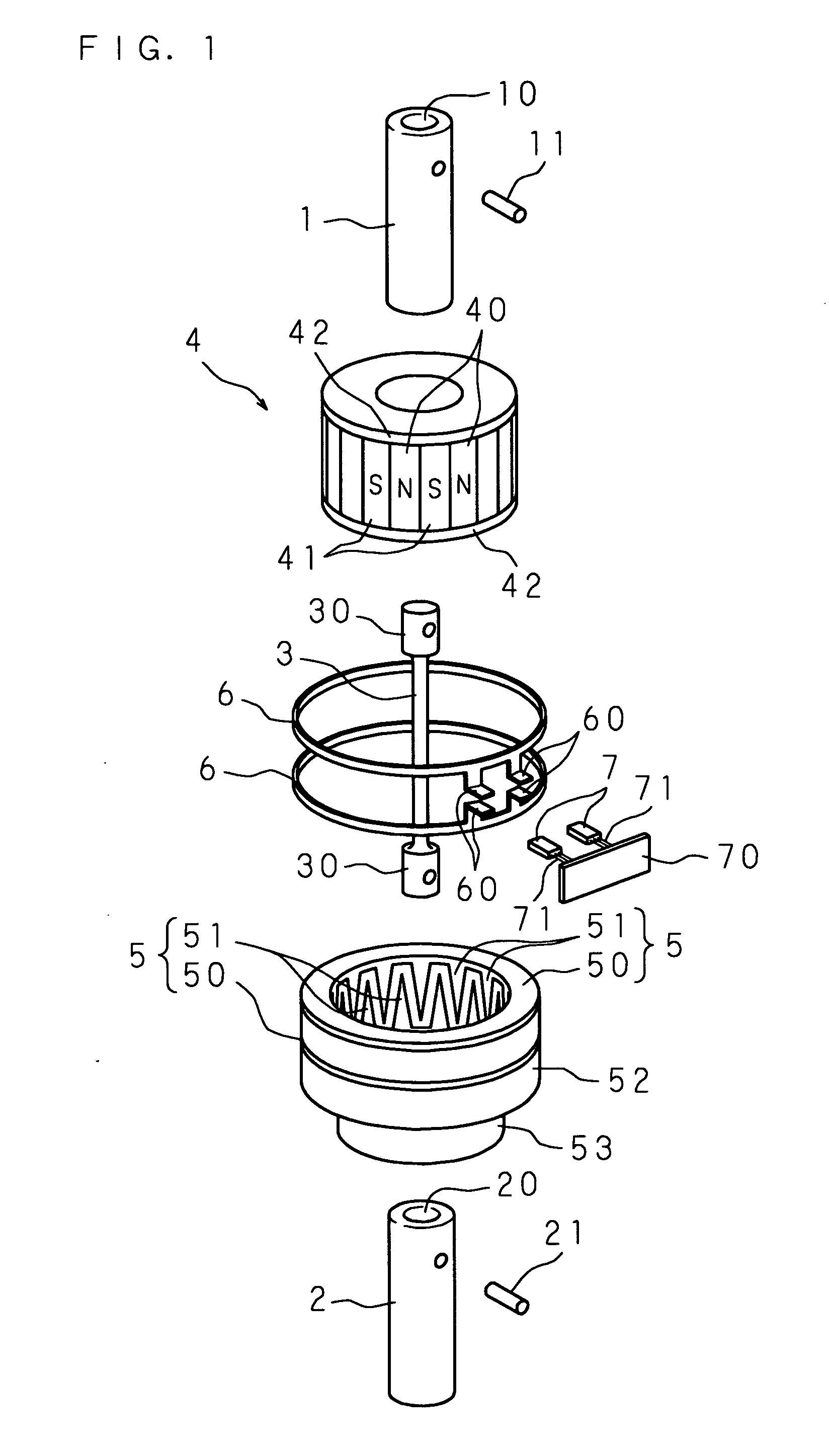
[0083]FIG. 1 is an exploded perspective view of a torque detecting apparatus showing Embodiment 1 of the present invention and FIG. 2 is a longitudinally cross sectional view of the same in its assembled state.
[0084] The torque detecting apparatus according to the present invention is designed for detecting the torque exerted on two rotating members or shafts (a first shaft 1 and a second shaft 2) which are joined coaxially to each other by a torsion bar 3 and thus comprises a cylindrical magnet 4 arranged rotatable together with the first shaft 1, a pair of yoke rings 5 and 5 arranged rotatable together with the second shaft 2, a pair of magnetism collecting rings 6 and 6 provided to elastically surround the yoke rings 5 and 5 respectively for receiving the magnetic flux generated in the yoke rings 5 and 5, and a pair of magnetic sensors 7 and 7 provided between the two magnetism collecting rings 6 and 6 to act as a group (two in the drawings) of detectors which will be explained ...
embodiment 3
[0120]FIG. 12 is a longitudinally cross sectional view of a torque detecting apparatus showing Embodiment 3 of the present invention. The torque detecting apparatus has upper one in the drawing of two magnetism collecting rings 6 and 6 provided integrally on the inner side at one end of a cylindrical holder 64 made of a resin material and securely fitted via the cylindrical holder 64 into a housing 8. The other or lower magnetism collecting ring 6 is held in the inner side at the other end of the cylindrical holder 64 for movement along the axial direction and comes at the lowermost end into direct contact with an adjusting nut (adjusting means) 65 which is screwed in an opening provided in the side of the cylindrical holder 64. The other arrangement of this embodiment is identical to that of the torque detecting apparatus shown in FIG. 2 where like components are denoted by like numerals as those shown in FIG. 2 and their construction and action will be explained in no more detail....
embodiment 4
[0123]FIG. 13 is a cross sectional view of a torque detecting apparatus showing Embodiment 4 of the present invention. FIG. 14 is a schematic exploded perspective view of the same and FIG. 15 is an explanatory view of a magnetic circuit generated when a rotating body is turned in one direction.
[0124] The torque detecting apparatus denoted by A comprises a pair of magnetism collecting rings 6 and 6 provided circumferentially of a magnetic circuit generating member 12, which is mounted on a first shaft 1 and a second shaft 2 joined coaxially to each other by a torsion bar 3, as separated from each other along the axial direction for collecting the magnetism generated by the magnetic circuit generating member 12, a pair of magnetic shielding layers 9 and 9 for magnetically shielding the magnetism collecting rings 6 and 6 respectively from the external magnetic field, a magnetic sensor 7 provided as a detector for detecting a torque exerted on the first shaft 1 from the density of a ma...
PUM
| Property | Measurement | Unit |
|---|---|---|
| magnetic field | aaaaa | aaaaa |
| density | aaaaa | aaaaa |
| magnetic flux | aaaaa | aaaaa |
Abstract
Description
Claims
Application Information
 - R&D
- Intellectual Property
- Life Sciences
- Materials
- Tech Scout
- Unparalleled Data Quality
- Higher Quality Content
- 60% Fewer Hallucinations
Browse by: Latest US Patents, China's latest patents, Technical Efficacy Thesaurus, Application Domain, Technology Topic, Popular Technical Reports.
© 2025 PatSnap. All rights reserved.Legal|Privacy policy|Modern Slavery Act Transparency Statement|Sitemap|About US| Contact US: help@patsnap.com