
Tracheostoma spacer, tracheotomy method, and device for inserting a tracheostoma spacer

a tracheostoma spacer and tracheotomy technology, which is applied in the direction of tracheal tubes, medical devices, other medical devices, etc., can solve the problems of inability to insert the trachea in time, large and bulky cannulae or tubes, and the risk of incorrect incision is very soon found to be difficult or even impossible, so as to minimize the risk of injury and the danger of incorrect incision, the effect of preventing the damage of the posterior wall of the tra

Active Publication Date: 2008-02-07
BREATHE TECHNOLOGIES INC
View PDF99 Cites 21 Cited by
  • Summary
  • Abstract
  • Description
  • Claims
  • Application Information

AI Technical Summary

Benefits of technology

[0006] One aspect of the invention is directed to a tracheostoma spacer, a tracheotomy method and a device for inserting such a tracheostoma spacer, in which the tracheostoma can be made smaller and / or does not have to be expanded as much and in which the spacer can perform some dilatation of the tracheostoma and conform to the person's anatomy.
[0048] An abutment can also be provided at the tip of the cutting instrument or on the cover sleeve and prevents the device from being pushed into the trachea beyond a defined depth. Damage to the posterior wall of the trachea can be advantageously prevented by the abutment.

Problems solved by technology

A problem of percutaneous tracheotomy methods is that the tracheostoma closes again within a very short time after removal of a cannula or tube placed in the tracheostoma, and renewed insertion is very soon found to be difficult or even impossible.
A disadvantage of the known cannulae or tubes is that they are large and bulky; they protrude from the patient's neck, they extend deep into the tracheal lumen, and they have relatively thick walls and large fixed diameters.
Therefore, they are obtrusive to the patient and require a relatively large tracheostoma to be made to accommodate the cannula or tube.
Also they do not assist in the dilatation of the trachesotoma, and they do not conform to patient anatomy, rather the anatomy conforms to the rigidity of the cannula or tube.

Method used


Image

  • Tracheostoma spacer, tracheotomy method, and device for inserting a tracheostoma spacer
  • Tracheostoma spacer, tracheotomy method, and device for inserting a tracheostoma spacer
  • Tracheostoma spacer, tracheotomy method, and device for inserting a tracheostoma spacer

Examples


Embodiment Construction

[0063] Identical or similar features in the drawings are provided with identical reference labels.

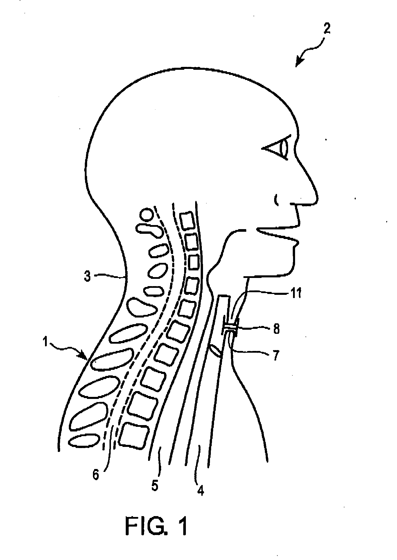
[0064] A schematic partial section through the upper body 1 of a patient 2 is shown in FIG. 1. In the region of the neck 3, the trachea 4 is preferably situated in front of the oesophagus 5 and the spinal column 6. To help the patient 2 breathe, a percutaneous tracheotomy has been performed in which an opening in the trachea 4 has been made through the skin, this opening being referred to as a tracheostoma 7. To prevent the tracheostoma 7 from quickly closing again, a tracheostoma spacer 8 according to the invention is positioned in the tracheostoma 7.

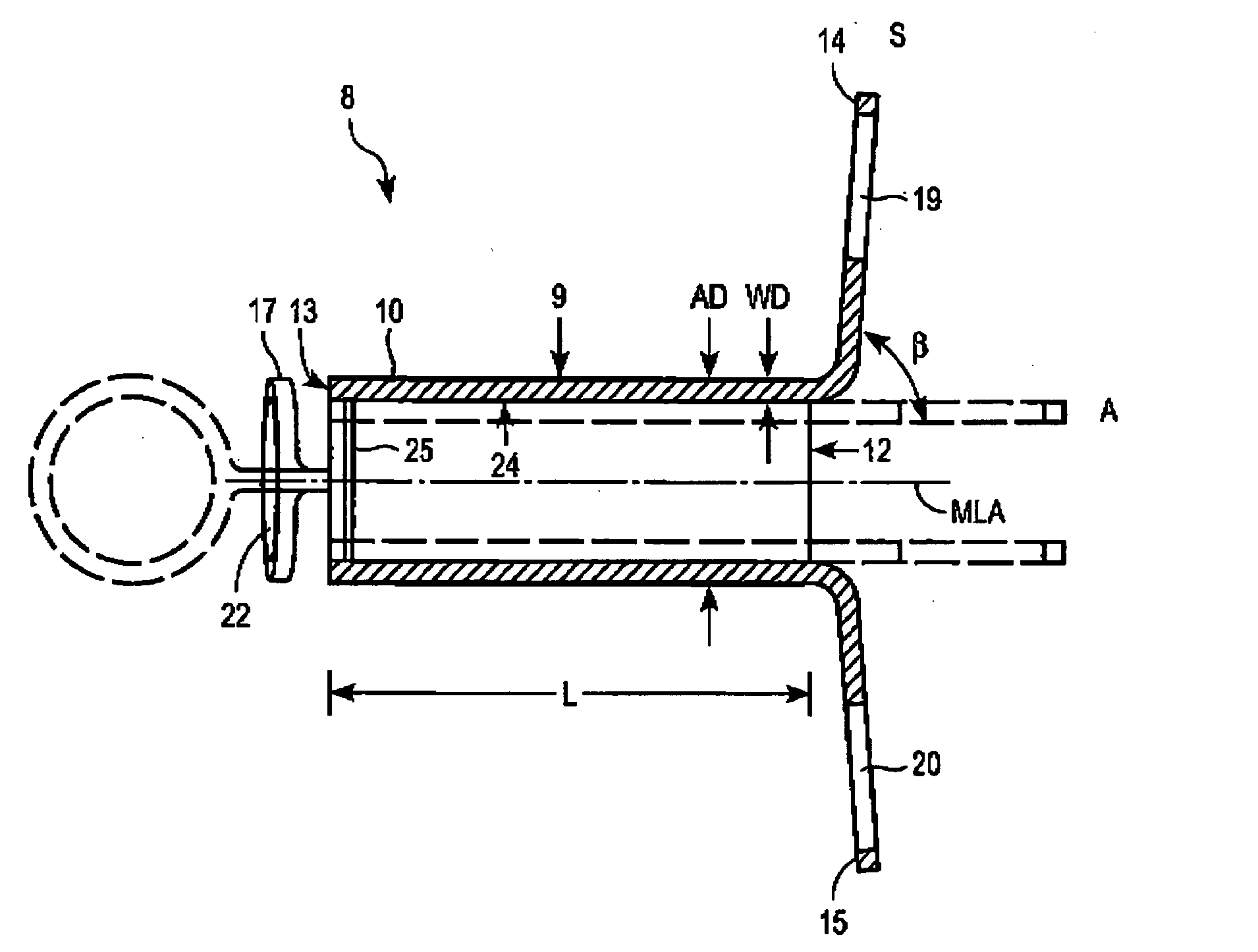
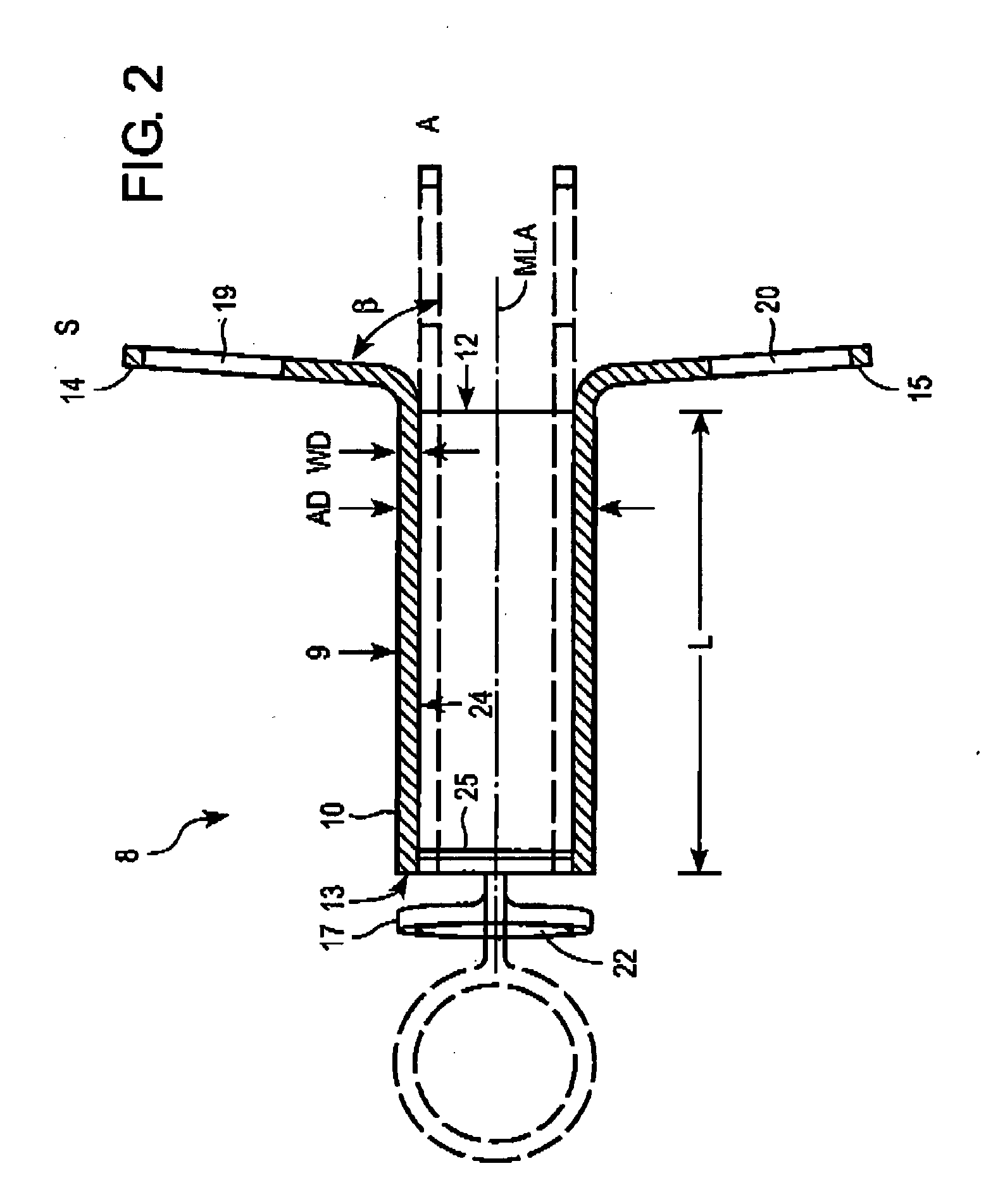
[0065] The tracheostoma spacer 8 is shown in more detail in FIGS. 2 and 3. The tracheostoma spacer 8 has a tubular support framework 9. The support framework 9 is able to self-expand from an initial state A (shown by broken lines) to a supporting state S of increased diameter (shown by solid lines). The length L of the support framework ...


PUM


Abstract

The invention relates to a tracheostoma spacer with a tubular support framework. The support framework can be expand from an initial state to a supporting state of increased diameter and has a fixing element at the ends. The tracheostoma spacer is intended for use as a spacer in a tracheostoma (an opening in the trachea). The invention further relates to a device for inserting a tracheostoma spacer into a tracheostoma with a cutting instrument in the form of a trocar, the tracheostoma spacer being able to be positioned on the shaft of said trocar. A cover sleeve is also provided which can be moved on the shaft over a tracheostoma spacer positioned there.

Description

PRIORITY INFORMATION [0001] This application claims priority to U.S. Provisional Patent Application Ser. No. 60 / 801,104 filed May 18, 2006, entitled “Tracheostomy Placeholder and Systems and Methods Relating to a Tracheostomy Placeholder,” the disclosure of which is incorporated herein by reference in its entirety.FIELD OF INVENTION [0002] The invention relates to a tracheostoma spacer with a tubular support framework, to a tracheotomy method, and to a device for inserting a tracheostoma spacer. DESCRIPTION OF RELATED ART [0003] Tracheotomies are medical procedures carried out in situations where a person has to be intubated for a length of time, where malformations, diseases or injuries of the upper airways lead to acute closure, or where there is a threat of suffocation. A surgically established opening in the trachea is known as a tracheostoma. Several methods for creating such a tracheostoma are known: percutaneous dilation tracheotomy, percutaneous puncture tracheotomy, surgica...

Claims


Application Information

Patent Timeline
IPC IPC(8): A61M16/04
CPCA61M16/0434A61M16/0468A61M16/0472A61M16/0488A61M16/0477A61M2205/0222A61M2205/0266A61M2202/20A61M2202/0078
Inventor FREITAG, LUTZ
Owner BREATHE TECHNOLOGIES INC
Learn More