Thermoelectric structure and use of the thermoelectric structure to form a textile structure

Inactive Publication Date: 2008-02-07
COMMISSARIAT A LENERGIE ATOMIQUE ET AUX ENERGIES ALTERNATIVES
View PDF8 Cites 33 Cited by
  • Summary
  • Abstract
  • Description
  • Claims
  • Application Information

AI Technical Summary

Benefits of technology

[0011]Furthermore, a thermoelectric structure according to the invention can be used to form a textile structure, the dielectric wires then being constituted by textile fibers. Fabrication of a textile structure integrating a thermoelectric structure is therefore greatly facilitated as compared with the prior art, for it is performed in a single operation where the tex

Problems solved by technology

This type of known thermoelectric structure is not however totally satisfactory.
Fabrication of the thermoelectric structure does in fact remain complex and costly, in particular on account of production of the substrate.
The applications of such a thermoelectric structure are moreover limited by the flexibility of the substrate which remains low.
Integrating the latter in a textile structure when manufacturing a product int

Method used


Image

  • Thermoelectric structure and use of the thermoelectric structure to form a textile structure
  • Thermoelectric structure and use of the thermoelectric structure to form a textile structure

Examples


Example

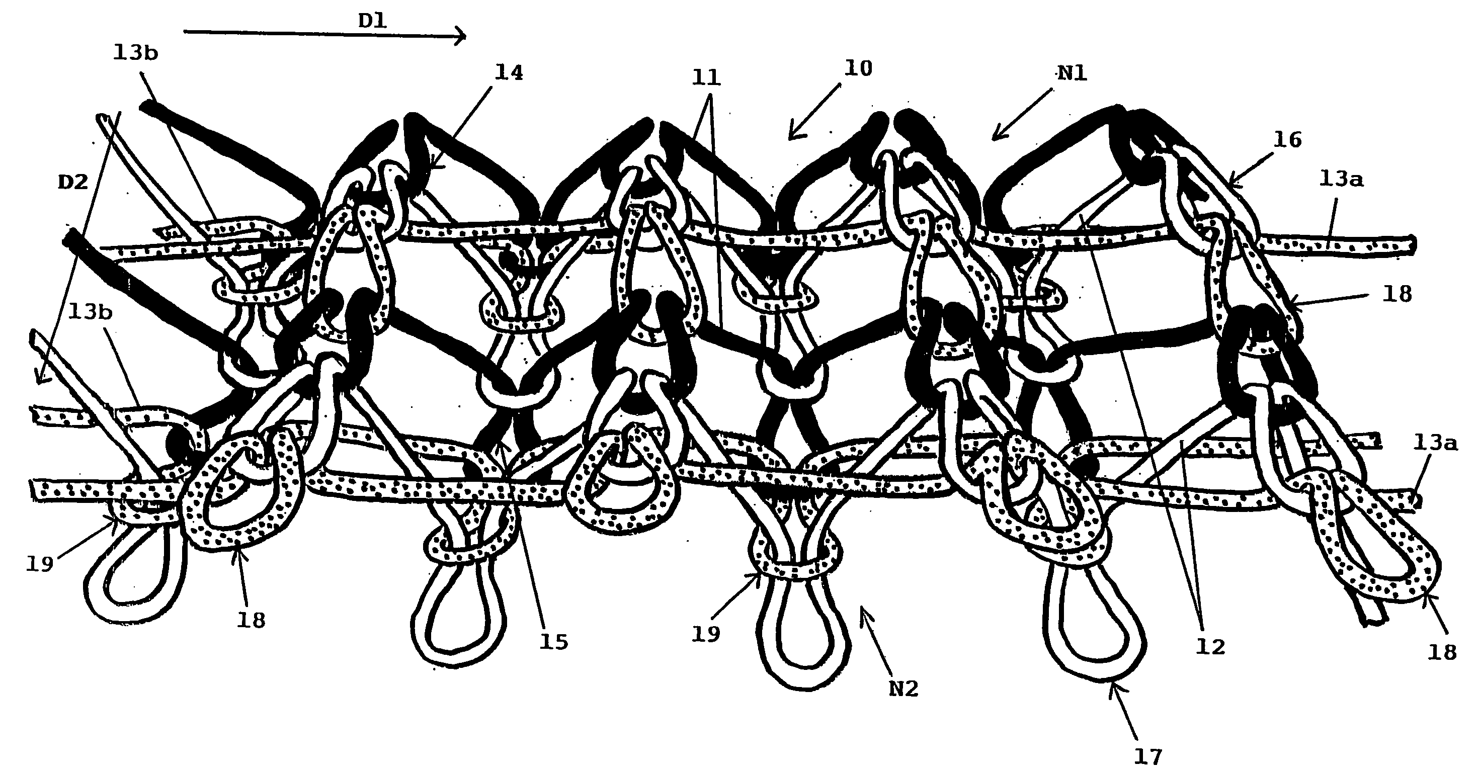
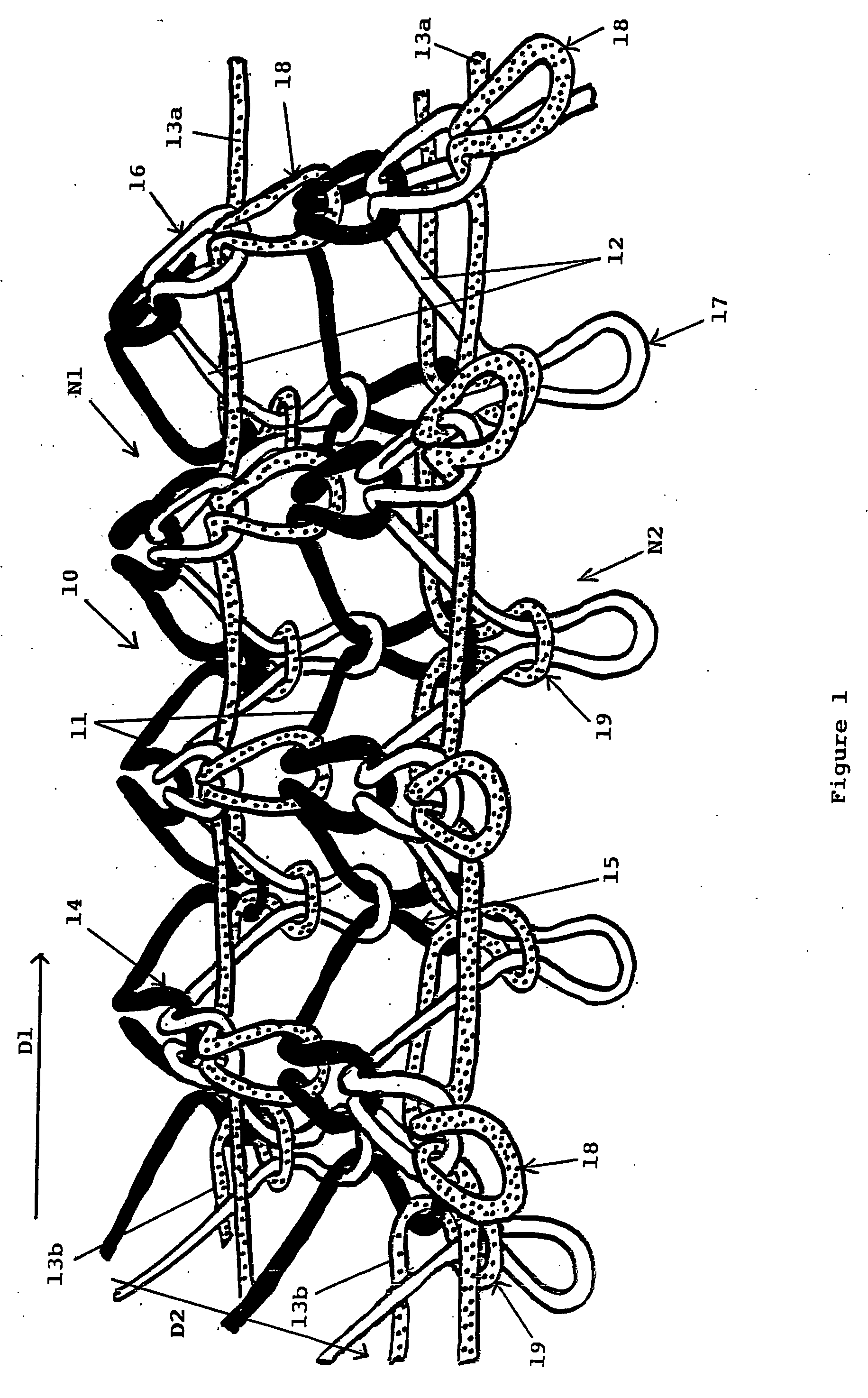
[0013]FIG. 1 illustrates a strip of an example embodiment of a thermoelectric structure 10 according to the invention. The thermoelectric structure 10 is achieved in this example by Jacquard knitting. It combines first and second conducting wires 11 and 12 of different natures, respectively represented in black and in white, and high 13a and low 13b dielectric wires made from electrically insulating material and represented by dashed lines. For the knitting, two bobbins of dielectric wires 13a and 13b and two bobbins of conducting wires 11 and 12 of different natures simultaneously feed the needles of a loom adapted for production of the thermoelectric structure 10 which will be described hereafter. The knitting process is well known as such and the method for performing same can easily be determined merely in the light of the structure to be produced. The knitting process will therefore not be described in detail in the scope of the present description.

[0014]The conducting wires 11...


PUM


Abstract

The thermoelectric structure is formed by a network of wires oriented substantially in a weft direction of the structure. It comprises first and second conducting wires of different kinds, interwoven to form cold and hot junctions distributed respectively in a top plane and a bottom plane. The junctions are alternately cold and hot along any one conducting wire. The thermoelectric structure comprises at least one high dielectric wire in the top plane, and at least one low dielectric wire in the bottom plane. The dielectric wires are interwoven with the first and second conducting wires so as to keep the top and bottom planes at a distance from one another.

Description

BACKGROUND OF THE INVENTION[0001]The invention relates to a thermoelectric structure formed by a network of wires oriented substantially in a weft direction of the structure, comprising first and second conducting wires of different natures that are interwoven to form cold and hot junctions distributed respectively in two planes, a top plane and a bottom plane, the junctions being alternately cold and hot along any one conducting wire.[0002]It also relates to the use of such a thermoelectric structure to form a textile structure.STATE OF THE ART[0003]This type of thermoelectric structure constitutes a thermoelectric converter enabling for example an electromotive force to be generated by Seebeck effect when a temperature gradient is applied between the cold and hot junctions. In particular, when such a structure is integrated in the material used for making an item of clothing, the temperature gradient that occurs in service between the media separated by said material results in a ...

Claims


Application Information

Patent Timeline
IPC IPC(8): H01L35/02
CPCH01L35/32D04B1/14D10B2401/16D10B2403/0114H10N10/17
Inventor PLISSONNIER, MARCSALVILANIER, THIERRYCOULAUX, DENIS
Owner COMMISSARIAT A LENERGIE ATOMIQUE ET AUX ENERGIES ALTERNATIVES
Why Eureka
Try Eureka