
Rotating Scraper

a scraper and rotating technology, applied in the field of scrapers, can solve the problems of adversely affecting the ability of the disk to till the soil and mulch the debris, and the tendency of the soil to accumulate on a concave surfa

Inactive Publication Date: 2008-02-07
DISCMASTER
View PDF40 Cites 12 Cited by
  • Summary
  • Abstract
  • Description
  • Claims
  • Application Information

AI Technical Summary

Benefits of technology

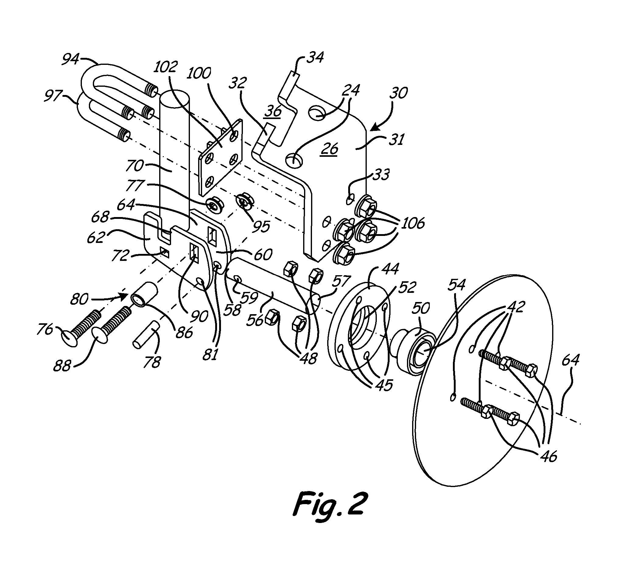
[0008] The present invention includes a scraper for mounting to a tool bar of a farm implement having at least one rotating disk for tilling soil. The scraper includes a support mounted to the tool bar and a shaft pivotally attached to and extending from the support where the shaft has a central axis. A scraper blade is rotatably attached to an end of the shaft and the scraper blade comprises a perimeter wherein the shaft pivots to engage a side surface of the rotating disk to prevent soil from accumulating on the side surface and also prevents debris from accumulating between the side surface and the scraper blade.
[0009] The present invention also includes a farm implement having at least one rotating disk for tilling soil and a tool bar proximate the at least one rotating disk. The farm implement also includes at least one scraper attached to the tool bar where the scraper includes a support mounted to the tool bar and a shaft pivotally attached to and extending from the support where the shaft has a central axis. A scraper blade is rotatably attached to an end of the shaft and wherein the scraper blade has a perimeter wherein the shaft pivots to engage a side surface of the rotating disk to prevent soil from accumulating on the side surface and prevents debris from accumulating between the side surface and the scraper blade.

Problems solved by technology

However, when the soil is moist or wet while being tilled with a tandem disk, the soil has a tendency of accumulating on a concave surface of the disks.
However, the static, rigid scrapers have a tendency of bending or rotating away from the concave surface of the disk and thereby allow the wet soil to accumulate on the concave surface of the disk which adversely affects the ability of the disk to till the soil and mulch the debris.
Further, the debris has a tendency of collecting between the static scraper and the disk which may prevent the disk from rotating.

Method used


Image

  • Rotating Scraper
  • Rotating Scraper
  • Rotating Scraper

Examples


Embodiment Construction

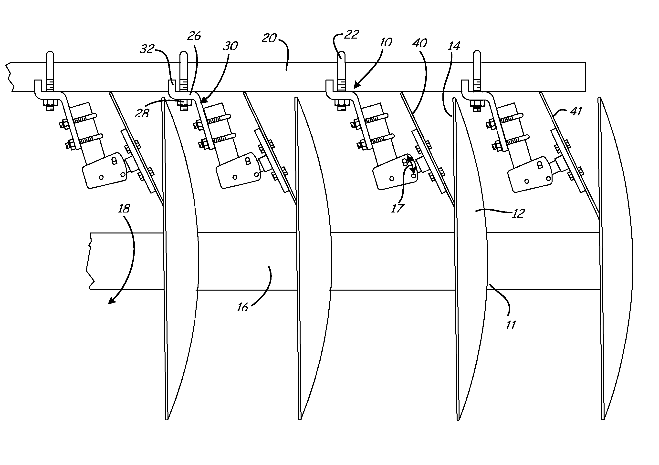
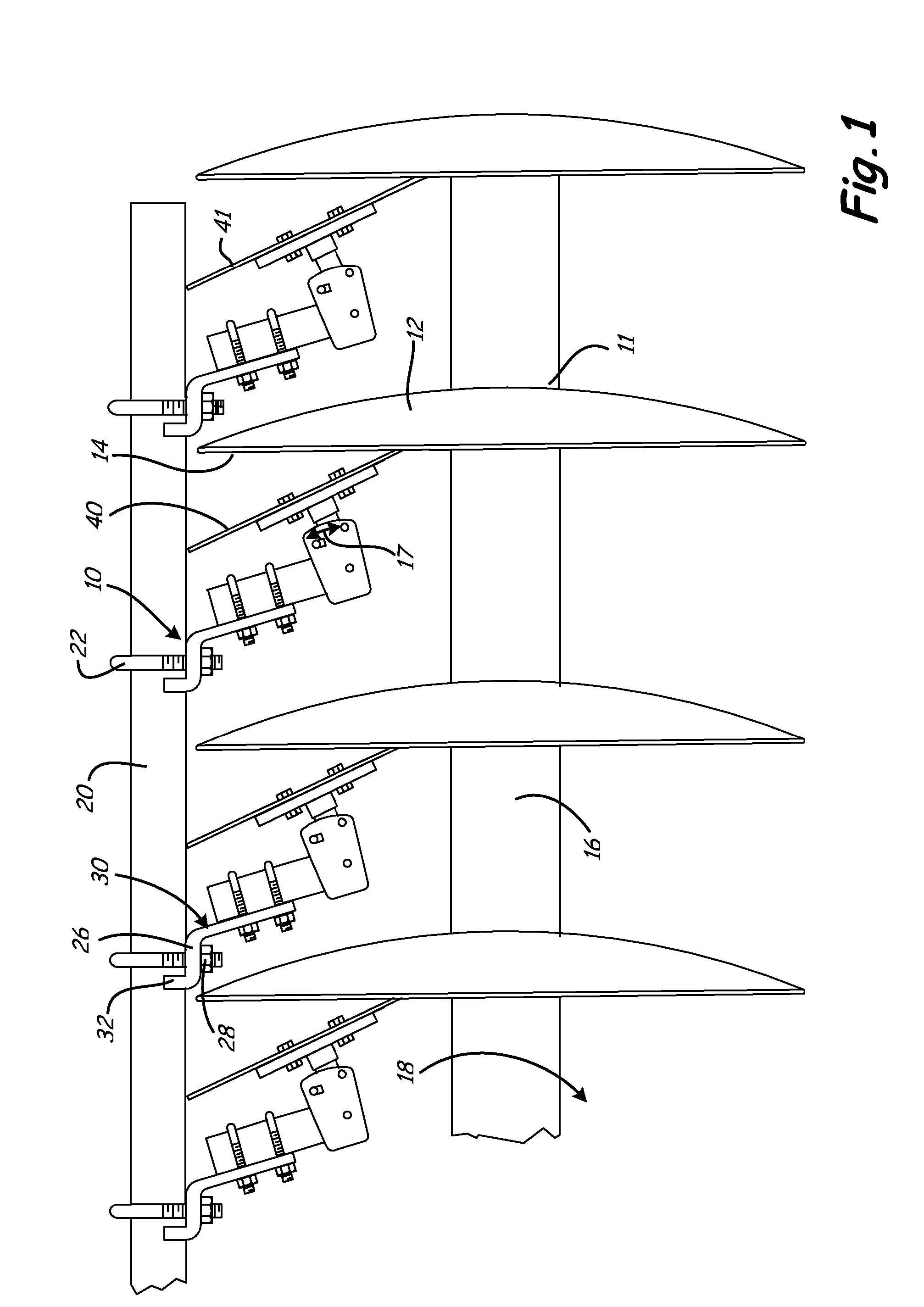
[0013] A rotating scraper for a disk blade attached to a farm implement is generally illustrated in FIG. 1 at 10. Each rotating scraper 10 includes a scraper blade 40 that rotatably engages a side surface 14 of a disk blade 12 to prevent soil and / or debris from accumulating on the disk blade 12. Typically, the side surface 14 of the disk blade 12 is concave, however the side surface 14 could also be substantially flat or convex.

[0014] Typically, the rotating scraper 10 is attached to a tool bar 20 of a tandem disk where the disk blades 12 are secured to a shaft 16 to form a gang 13 of a tandem disk. The disks 12 rotate along with the shaft 16 in the rotational direction of arrow 18. While the rotating scraper 10 is typically utilized with a tandem disk, the rotating scraper 10 can also be utilized with disks on other agricultural equipment.

[0015] Typically, the disk blades 12 have a circular perimeter 11 that penetrates the ground between about one inch and about six inches depend...


PUM


Abstract

A scraper for mounting to a tool bar of a farm implement having at least one rotating disk for tilling soil, including a support mounted to the tool bar and a shaft pivotally attached to and extending from the support where the shaft has a central axis. A scraper blade is rotatably attached to an end of the shaft and the scraper blade comprises a perimeter wherein the shaft pivots to rotatably engage a side surface of the rotating disk to prevent soil from accumulating on the side surface and prevents debris from accumulating between the side surface and the scraper blade.

Description

CROSS REFERENCE TO RELATED APPLICATION(S) [0001] This application is a continuation-in-part of U.S. patent application Ser. No. 11 / 524,969 which was filed on Sep. 21, 2006, which is incorporated by reference herein in its entirety, which claims the benefit of U.S. Provisional Application Ser. No. 60 / 734,824 filed on Nov. 9, 2005 which is incorporated by reference herein in its entirety.BACKGROUND OF THE INVENTION [0002] The present invention relates to a scraper for a farm implement. More particularly, the present invention relates to a scraper having a rotating blade that is attached to a farm implement. [0003] There are many types of farm implements that are used to till soil in preparation for seeding or planting. One such farm implement is a tandem disk. [0004] A typical configuration of a tandem disk includes a front gang of disks proximate a front end of the tandem and a back gang of disks proximate a back end of the tandem disk. The front gang of disks are configured generall...

Claims


Application Information

Patent Timeline
IPC IPC(8): A01B15/16
CPCA01B23/06
Inventor MEIDINGER, JAMES
Owner DISCMASTER
Learn More