Automatic Clutch Mechanism, Automatic Clutch Mechanism for Straddle-Type Vehicle, and Straddle-Type Vehicle

a technology of automatic clutch and straddle-type vehicles, which is applied in the direction of clutches, coupling-brake combinations, control devices, etc., can solve the problem that the feeling of gear shifting cannot be effectively transmitted to the rider through the pedal, and achieve the effect of reducing the burden on the rider during pedal operation, facilitating the rider to operate the pedal, and generally small reaction force on the pedal

Inactive Publication Date: 2008-02-07
YAMAHA MOTOR CO LTD
View PDF8 Cites 6 Cited by
  • Summary
  • Abstract
  • Description
  • Claims
  • Application Information

AI Technical Summary

Benefits of technology

[0021] With the automatic clutch mechanism of the invention, the reaction force exerted on the pedal becomes generally small in comparison with the related art, and thus the burden on the rider during pedal operation is reduced, thereby making it easier for the rider to operate the pedal. When the clutch is disengaged by operating the pedal and a gear shift is performed, the reaction force exerted on the pedal becomes generally small in comparison with the related art. Therefore, at the time of gear shifting, the change in the reaction force exerted on the pedal is readily transmitted to the rider through the pedal.

Problems solved by technology

Therefore, the automatic clutch mechanism has a problem in that the feel of gear shifting is not effectively transmitted to the rider through the pedal.

Method used


Image

  • Automatic Clutch Mechanism, Automatic Clutch Mechanism for Straddle-Type Vehicle, and Straddle-Type Vehicle
  • Automatic Clutch Mechanism, Automatic Clutch Mechanism for Straddle-Type Vehicle, and Straddle-Type Vehicle
  • Automatic Clutch Mechanism, Automatic Clutch Mechanism for Straddle-Type Vehicle, and Straddle-Type Vehicle

Examples


Embodiment Construction

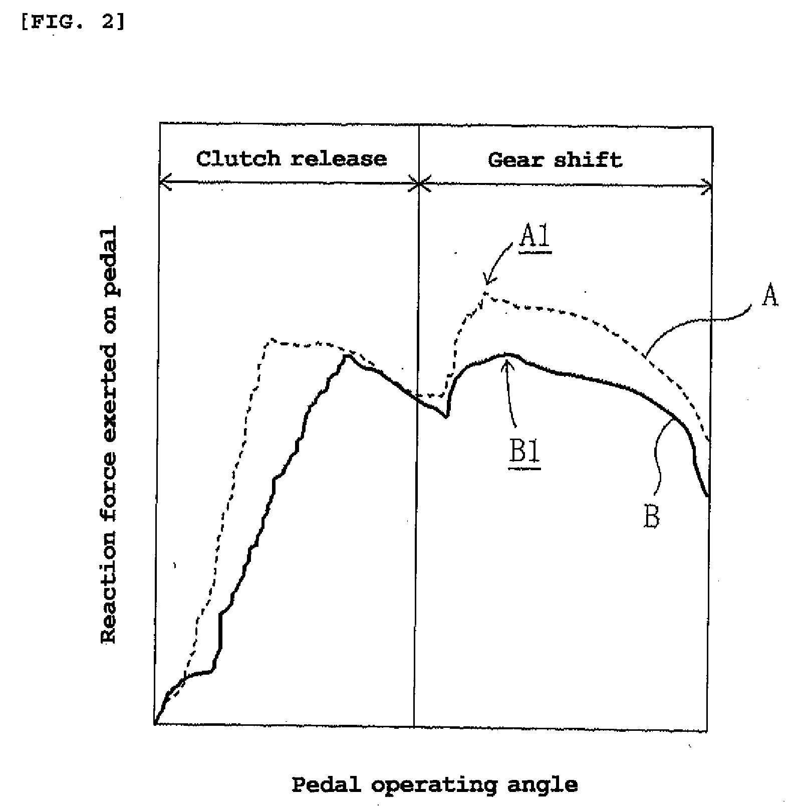
[0034] The inventors wish to improve the operability of a pedal in an automatic clutch mechanism by making the reaction force exerted on the pedal as small as possible. Further, the inventors believe that transmitting the feel of gear shifting to the rider through the pedal will make the steering of a straddle-type vehicle more fun. Thus, the inventors examined improvements that could be made to automatic clutch mechanisms according to the related art. The inventors considered the mechanism of the reaction force exerted on the pedal, and the reason why the feel of gear shifting is not readily transmitted to the rider through the pedal, as follows.

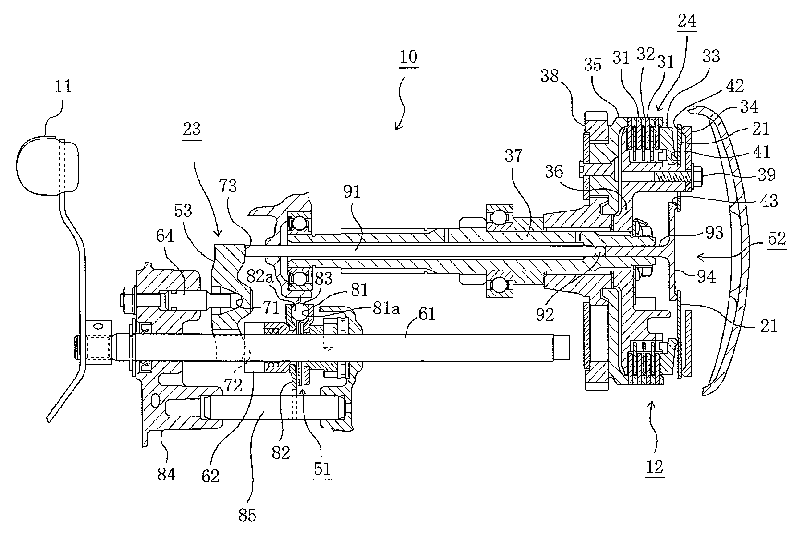
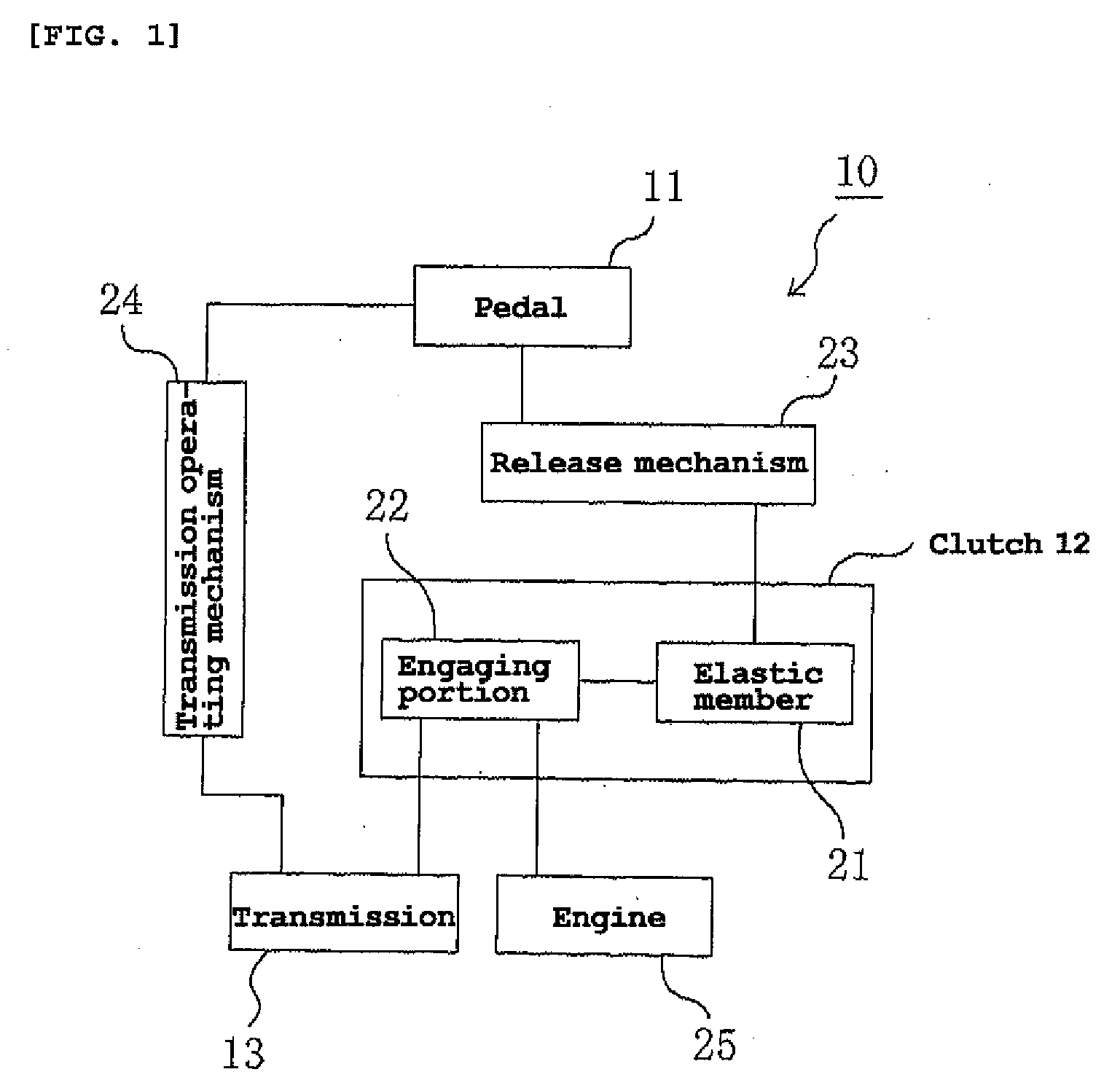
[0035] As shown in FIG. 1, an automatic clutch mechanism 10 includes a pedal 11, a clutch 12, and a transmission 13. Clutch 12 includes an engaging portion 22 for bringing transmission 13 and an engine 25 into engagement with each other by an elastic reaction force of an elastic member 21 inserted in clutch 12. Clutch 12 is operated by a r...


PUM


Abstract

An automatic clutch mechanism that allows the feel of gear shifting to be readily transmitted to a rider through a pedal. The automatic clutch mechanism shifts gears while disengaging a clutch in conjunction with one pedal operation. A transmission effects a gear shift in conjunction with a pedal operation. The clutch includes an elastic member, and an engaging portion for bringing the transmission and an engine into engagement with each other by the elastic reaction force of the elastic member. The elastic member has a gradient-decreasing range in which the gradient of a change in elastic load with respect to deformation of the elastic member decreases as the deformation increases. The gradient-decreasing range is included in the use range of the elastic member determined by operation of the clutch.

Description

RELATED APPLICATIONS [0001] This application claims the benefit of priority under 35 USC 119 of Japanese patent application nos. 2006-212621, filed on Aug. 3, 2006, which application is hereby incorporated by reference in its entirety. BACKGROUND OF THE INVENTION [0002] 1. Field of the Invention [0003] The present invention relates to an automatic clutch mechanism, and more specifically to an automatic clutch mechanism suitable for use in straddle-type vehicles such as a motorcycle or ATV. [0004] 2. Description of Related Art [0005] With a view to achieving improved operability for the rider, a straddle-type vehicle equipped with an automatic clutch mechanism has been proposed for effecting clutch disengagement / engagement and gear shift simultaneously solely by operating a shift pedal with a foot (for example, see JP-A-2005-42910). In JP-A-2005-42910, a coil spring (elastic member) urges a pressure plate to bring a friction plate and a clutch plate into press contact with each other...

Claims


Application Information

Patent Timeline
Patent Type & Authority Applications(United States)
IPC IPC(8): B60W10/02B60W10/10B60K23/02F16D13/56F16D13/52
CPCF16D13/52F16D13/583F16D13/56
Inventor YAMASHITA, KENJIMASUDA, TATSUYA
Owner YAMAHA MOTOR CO LTD
Why Eureka
Try Eureka