Integrated multi-purpose deployment field system

a multi-purpose deployment and field system technology, applied in the field of missions adaptable set of components for a multiple-purpose collapsible portable cart, can solve the problem that none of the existing carts can be converted to a versatile portable cart which can interchangeably, and achieve the effect of convenient assembly and disassembly

Inactive Publication Date: 2008-02-07
VALIANT ROCK LLC
View PDF90 Cites 10 Cited by
  • Summary
  • Abstract
  • Description
  • Claims
  • Application Information

AI Technical Summary

Benefits of technology

[0006] It is an object of the present invention to provide a versatile multi-purpose cart, which is quickly assembled or disassembled.
[0115] As a result, the convertible cart / utility table is mission adaptable for a variety of missions, and is not mission specific, such as for one particular task. The components break down into interchangeable parts, and are easily transported or stored for adaptability to a myriad of tasks in both friendly and hostile environments.

Problems solved by technology

However, none of the existing carts can be converted to a versatile portable cart which can interchangeably function as a rescue cart with a carrier for injured persons and be converted to a stationary utility table, as a portable canoe or boat cart which can be folded down and transported within the canoe or boat, as a game cart for transporting game over long, rough terrain, or as a gear cart, all of which can broken down into a carrying position, by hand or by back.

Method used


Image

  • Integrated multi-purpose deployment field system
  • Integrated multi-purpose deployment field system
  • Integrated multi-purpose deployment field system

Examples


Embodiment Construction

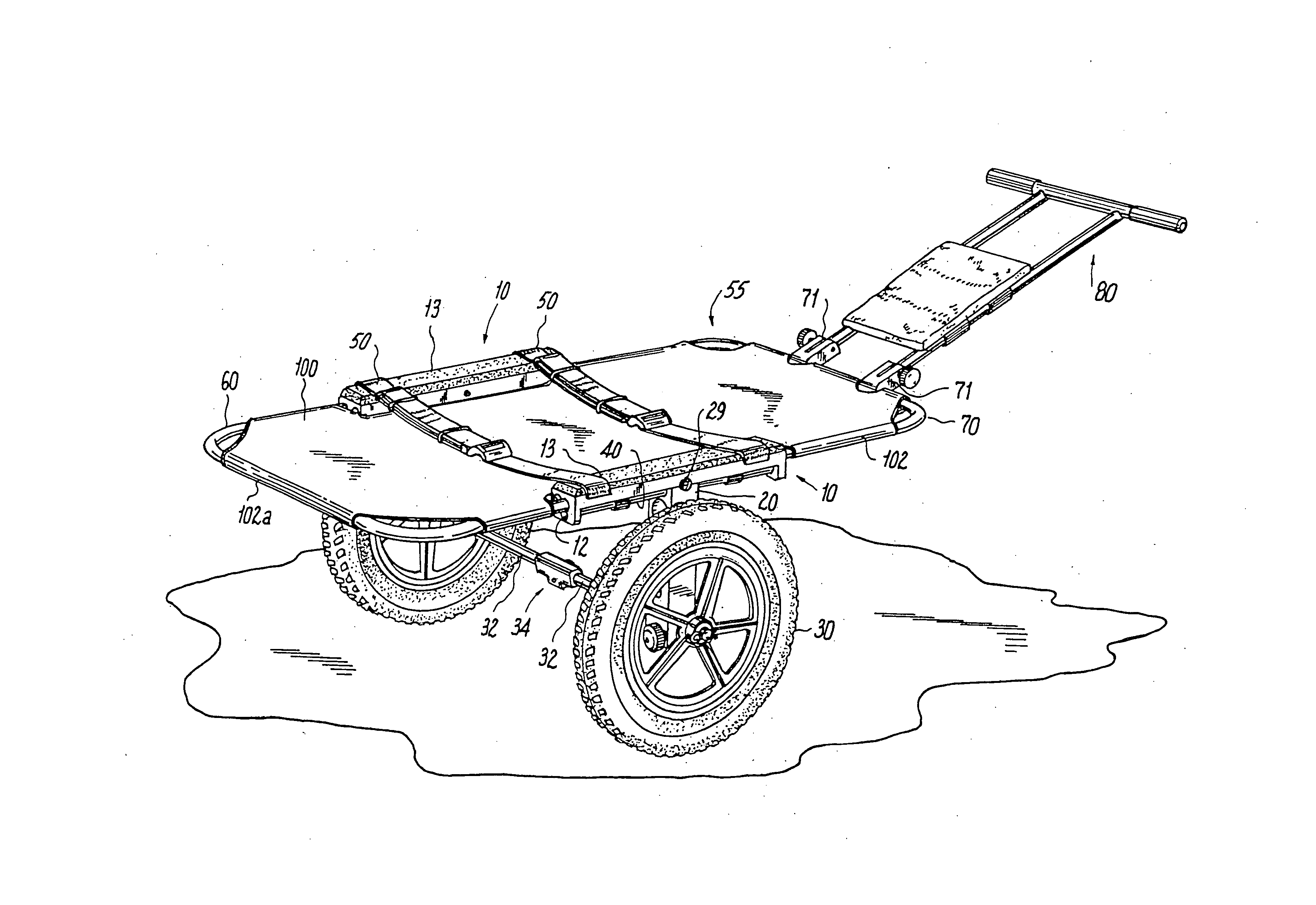
[0265] As shown in the drawing FIGS. 1-89, the present invention is directed to a mission-adaptable set of components forming a convertible cart / utility table. For example, the present invention may include foldable cart 1, having a load support for carrying a load, such as a boat, such as a canoe, which can also function as a game cart or a wagon for carrying gear in outdoor field applications.

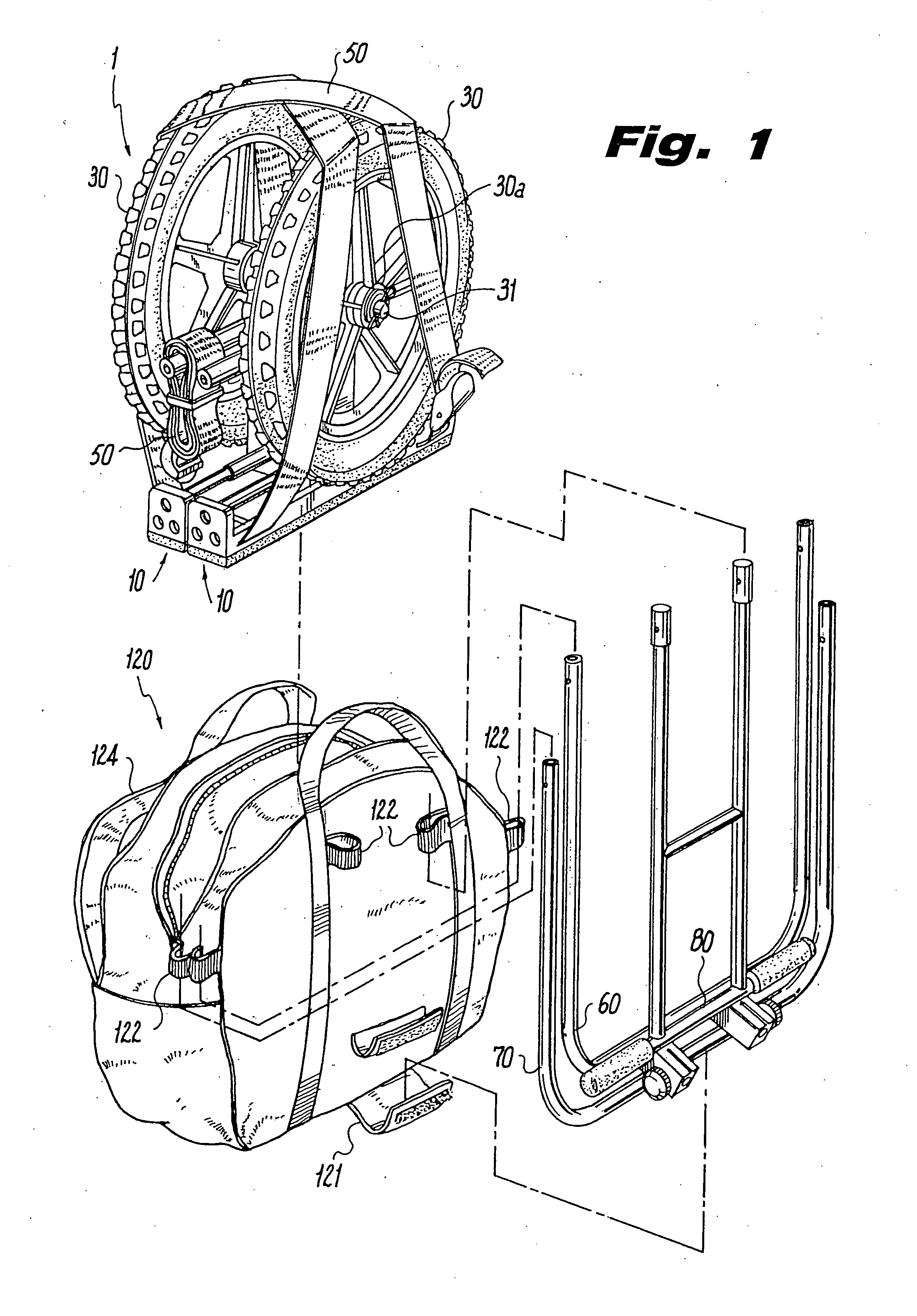
[0266]FIG. 1 shows cart 1 in a disassembled storage position with a pair of horizontal load support members 10 laid parallel adjacent to each other, supporting wheels 30 thereon. Wheels 30 are secured in place by a transverse connecting rod 31 through wheel hubs 30a and by one or more load securing straps 50. Disassembled storage cart 1 is inserted within carry bag 120, which includes ledge 121 and fabric loops 122 for holding bracket members 60, 70 and handle 80 outside of carry bag 120.

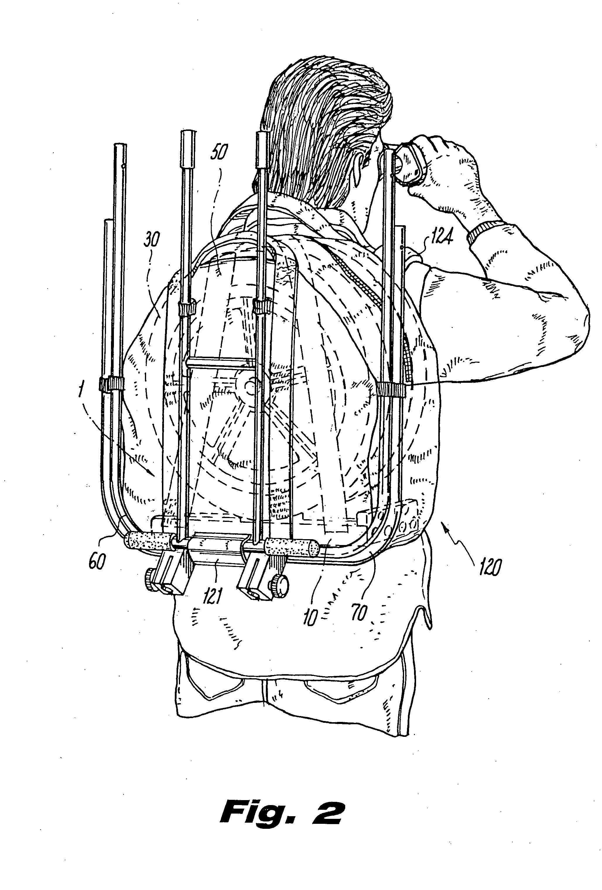
[0267] To transport portable cart 1 by hand carry straps 124 are attached to carry bag 120. Conversely a...


PUM

PropertyMeasurementUnit
widthaaaaaaaaaa
widthaaaaaaaaaa
sizeaaaaaaaaaa

Abstract

An integrated multi-purpose deployment field system enables a user to build a plurality of field pieces of equipment for field use in recreation, rescue, medicine, military operations, disaster relief and non-motorized cargo hauling. The system includes assembling the field equipment from a plurality of interchangeable T-shaped load support components. Each load support component has a generally horizontal load support member which is configured to support a particular type of load in the field, and a generally vertically extending support strut which extends from a midsection of the horizontal load support member. A load support attachment, such as a wheel axle or a cross brace, engages with each horizontal load support member, and joins the horizontal support members so that the T-shaped load support components, vertical struts, and load support attachments form a load bearing structure when assembled.

Description

RELATED APPLICATIONS [0001] This application is a continuation of patent application Ser. No. 11 / 396,157 filed Mar. 31, 2006 and patent application Ser. No. 11 / 396,158 filed Mar. 31, 2006, which applications in part disclose and claim priority from subject matter disclosed in my earlier filed patent application Ser. No. 10 / 686,948, filed Oct. 15, 2003, which is a continuation-in-part of application Ser. No. 10 / 431,839 filed May 7, 2003, which is a continuation of application Ser. No. 09 / 989,376, filed Aug. 24, 2001, now U.S. Pat. No. 6,561,529, which is a continuation in part of my provisional patent applications, Ser. No. 60 / 233,138, filed Sep. 18, 2000, and 60 / 246,014 filed Nov. 6, 2000 which both disclose in part subject matter disclosed in my earlier filed patent applications filed under Ser. No. 09 / 226,838 filed Jan. 7, 1999, now U.S. Pat. No. 6,142,491, Ser. No. 09 / 479,344 filed Jan. 7, 2000, now U.S. Pat. No. 6,164,671, and Ser. No. 09 / 745,116 filed Dec. 21, 2000, now U.S. Pa...

Claims


Application Information

Patent Timeline
Patent Type & Authority Applications(United States)
IPC IPC(8): B62B1/00A61G1/02B62B1/12B62B3/02B62B5/00B62B13/18
CPCA61G1/013A61G1/0231A61G13/105A61G2210/30A61G2220/10B62B1/002B62B1/008B62B1/12B62B3/02B62B5/0023B62B5/0079B62B13/18B62B2202/403B62B2202/42B62B2205/006B62B2205/04B62B2205/10B62B2206/02B62B2501/065A61G1/0212A61G1/0225A61G1/0287A61G1/0293
Inventor DARLING, CHARLES W. III
Owner VALIANT ROCK LLC
Why Eureka
Try Eureka