
Detachable propeller holder device

Active Publication Date: 2018-05-03
HAOXIANG ELECTRIC ENERGY KUNSHAN
View PDF0 Cites 5 Cited by
  • Summary
  • Abstract
  • Description
  • Claims
  • Application Information

AI Technical Summary

Benefits of technology

The present invention provides a detachable propeller holder device for UAVs that can be quickly assembled and disassembled. The device includes a propeller holder module, a fixed seat, and a motor module. Paddles and a buckling component are located on the propeller holder module, with two symmetrical elastic arms and hooks that are connected to limit portions on the fixed seat to secure the propeller holder module in place. The propeller holder module is connected to the motor module through the motor limit shaft, and is fixed with the buckling component through the limit portions of the fixed seat. The invention has a simple structure, easy installation, and no special tools required for assembly and disassemble.

Problems solved by technology

When these UAVs need to be replaced or disassembled, the special assembling and disassembling tool is required, which causes a certain inconveniency in usage.

Method used


Image

  • Detachable propeller holder device
  • Detachable propeller holder device
  • Detachable propeller holder device

Examples


first embodiment

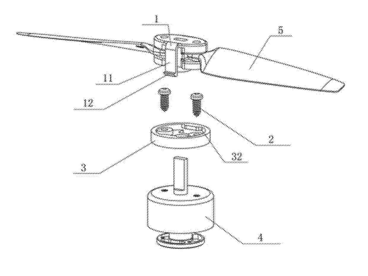
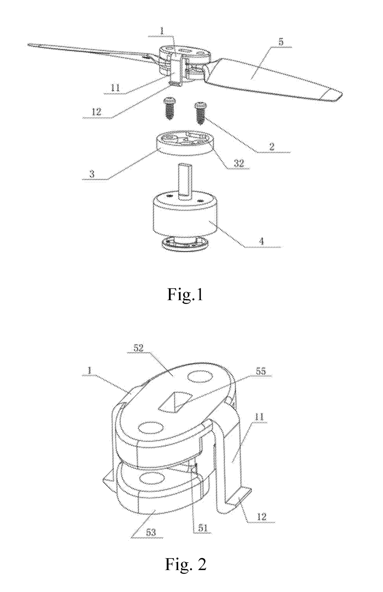
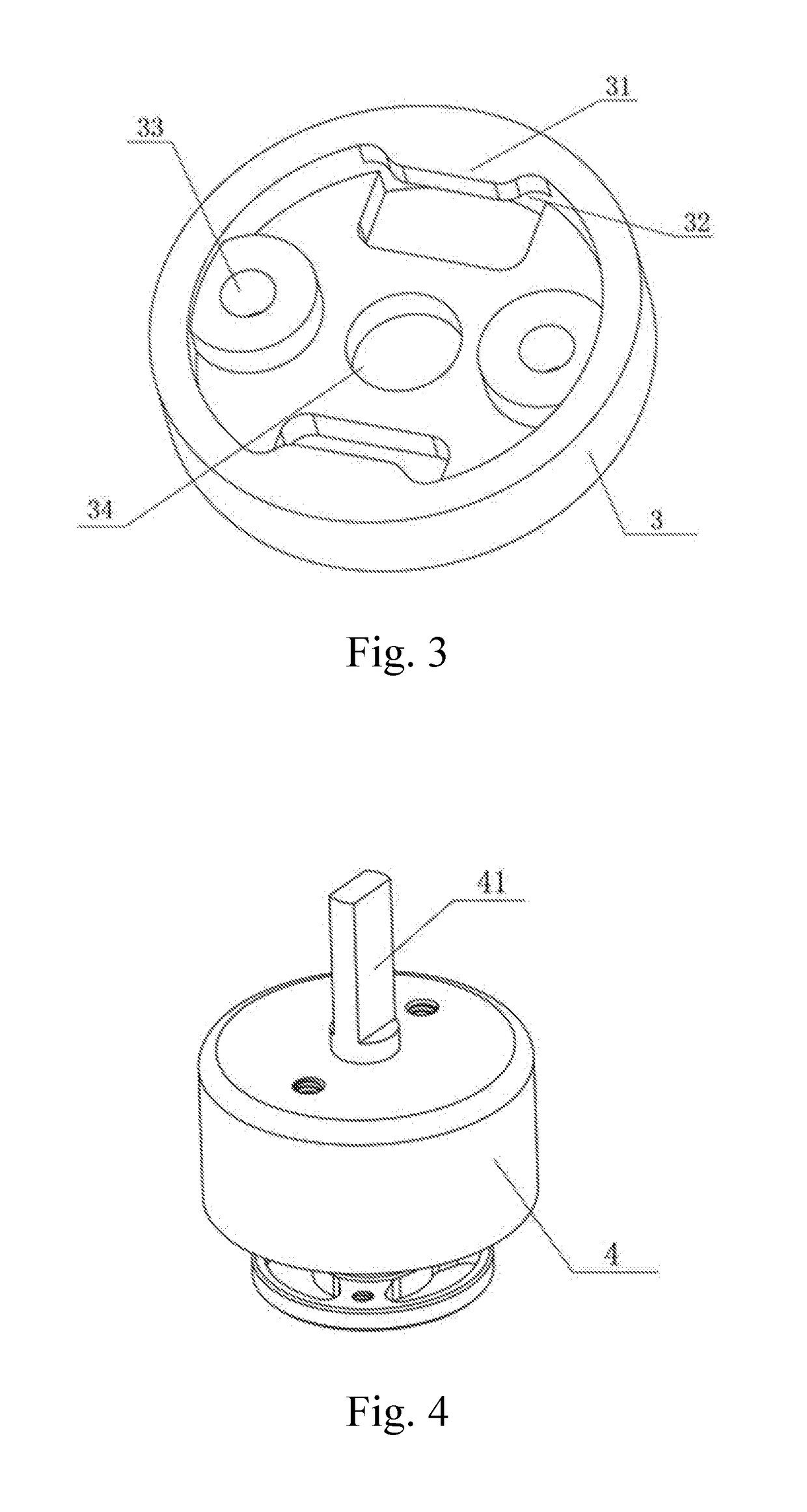
[0035]The present invention is a detachable propeller holder device UAVs (unmanned aerial vehicles) which is able to be quickly assembled and disassembled, comprising a propeller holder module 5 and a fixed seat 3, as shown in FIG. 1, a buckling component 1 is located on the propeller holder module 5 and is able to be made of any materials. The buckling component 1 comprises two elastic arms 11 which are symmetrically located at two sides of the propeller holder module 5 and two hooks 12 which are respectively located at an end of the two elastic arms 11. It can be seen from FIG. 3 that the fixed seat 3 comprises two fixture blocks 31 which respectively symmetrically extends from an edge of an upper surface to a center of the fixed seat 3, in such a manner that the fixture blocks 31 and a sidewall of the fixed seat 3 respectively form two limit portions 32, wherein the two limit portions 32 are symmetrical to each other and respectively corresponding to the hooks 12, the hooks 12 ar...

second embodiment

[0039]FIG. 8 is a structurally schematic diagram a propeller holder device according to a second embodiment of the present invention. It can be seen from FIG. 8 that the structure and the principle of the second embodiment are basically same as those of the first embodiment, both of which utilize the bucking component 1 and the limit portions 32 of the fixed seat 3 to achieve locking or unlocking. Differences between the first embodiment and second embodiment are as follows. In the first embodiment, the buckling component 1 and the propeller holder module 5 are integrally formed, and in the second embodiment, the buckling component 1 is fixed to a top portion of the propeller holder module 5 through screws or other fixing manners, which is illustrated through taking the screws as an example in the drawings.

[0040]To cooperate with the buckling component 1, the structure of the propeller holder module 5 and the motor module 4 varies accordingly, the structure of the fixed seat 3 is un...

third embodiment

[0043]FIG. 14 is a structurally schematic diagram of a propeller holder device according to a third embodiment of the present invention. The structure and the principle of the third embodiment are as same as those of the first embodiment and the second embodiment, all of which utilize the buckling component 1 and the limit portions 32 of the fixed seat 3 to achieve locking or unlocking.

[0044]In the first embodiment, the buckling component 1 and the propeller holder module 5 are integrally formed; but in the third embodiment, the buckling component 1 is fixed to a top portion of the propeller holder module 5 through screws or other fixing manners, which is illustrated through taking screws as an example in the drawings.

[0045]Different from the motor module provided by the first embodiment and the second embodiment, the motor module 4 provided by the third embodiment is fixed with the fixed seat 3 in a press-fit manner, as shown in FIG. 15, the fixed seat acts as a motor end cover, th...


PUM


Abstract

A detachable propeller holder device includes a propeller holder module, a fixed seat and a motor module. Paddles are located the propeller holder module, a buckling component is located on the propeller holder module, the buckling component includes two elastic arms and two hooks, the two elastic arms are symmetrically located at two sides of the propeller holder module, the hooks are respectively located at an end of the two elastic arms and are respectively buckled with two limit portions which are symmetrically located at the fixed seat, so as to fix the propeller holder module to the fixed seat. In the present invention, only the buckling component at the side of the propeller holder module is pinched by fingers to deform inwardly till the hooks are detached from the limit portions of the fixed seat, and then the propeller holder module is pulled upwardly to be removed.

Description

CROSS REFERENCE OF RELATED APPLICATION[0001]The present invention claims priority under 35 U.S.C. 119(a-d) to CN 201621457513.6, filed Dec. 28, 2016.BACKGROUND OF THE PRESENT INVENTIONField of Invention[0002]The present invention relates to a technical field of UAV (unmanned aerial vehicle), and more particularly to a detachable propeller holder device for a UAV.Description of Related Arts[0003]UAVs are unmanned aerial vehicles operated by radio remote control devices and their own program control devices, and are widely used in many fields such as military, agriculture, forestry, petroleum, electric power and environmental protection. At present, the domestic UAV market is hot, and the UAVs have been gradually expanded from the initial military field to the consumption field. The recognition and demand of UAVs by the general public are also gradually rising.[0004]In the UAV of the prior art, the paddles and the fuselage are integrally formed, the paddles are unable to be disassembl...

Claims


Application Information

Patent Timeline
IPC IPC(8): B64C11/10B64C39/02
CPCB64C11/10B64C39/024A63H27/12B64C2201/165B64C2201/042B64U30/291B64U50/13B64U50/19
Inventor TIAN, YUJIANG, WENYAN
Owner HAOXIANG ELECTRIC ENERGY KUNSHAN
Learn More