Self-adjusting hold-off trigger

a hold-off trigger and self-adjusting technology, applied in pulse manipulation, pulse technique, instruments, etc., can solve the problem of not considering the average duration of the measuremen

Inactive Publication Date: 2008-02-07
TEKTRONIX INC
View PDF7 Cites 20 Cited by
  • Summary
  • Abstract
  • Description
  • Claims
  • Application Information

AI Technical Summary

Problems solved by technology

When a state machine, which generates a trigger from the output of the trigger comparator, is set up for pulse width triggering, this may result in an error since the measured width from above the high level to below the low level may not accurately ...

Method used


Image

  • Self-adjusting hold-off trigger
  • Self-adjusting hold-off trigger
  • Self-adjusting hold-off trigger

Examples


Embodiment Construction

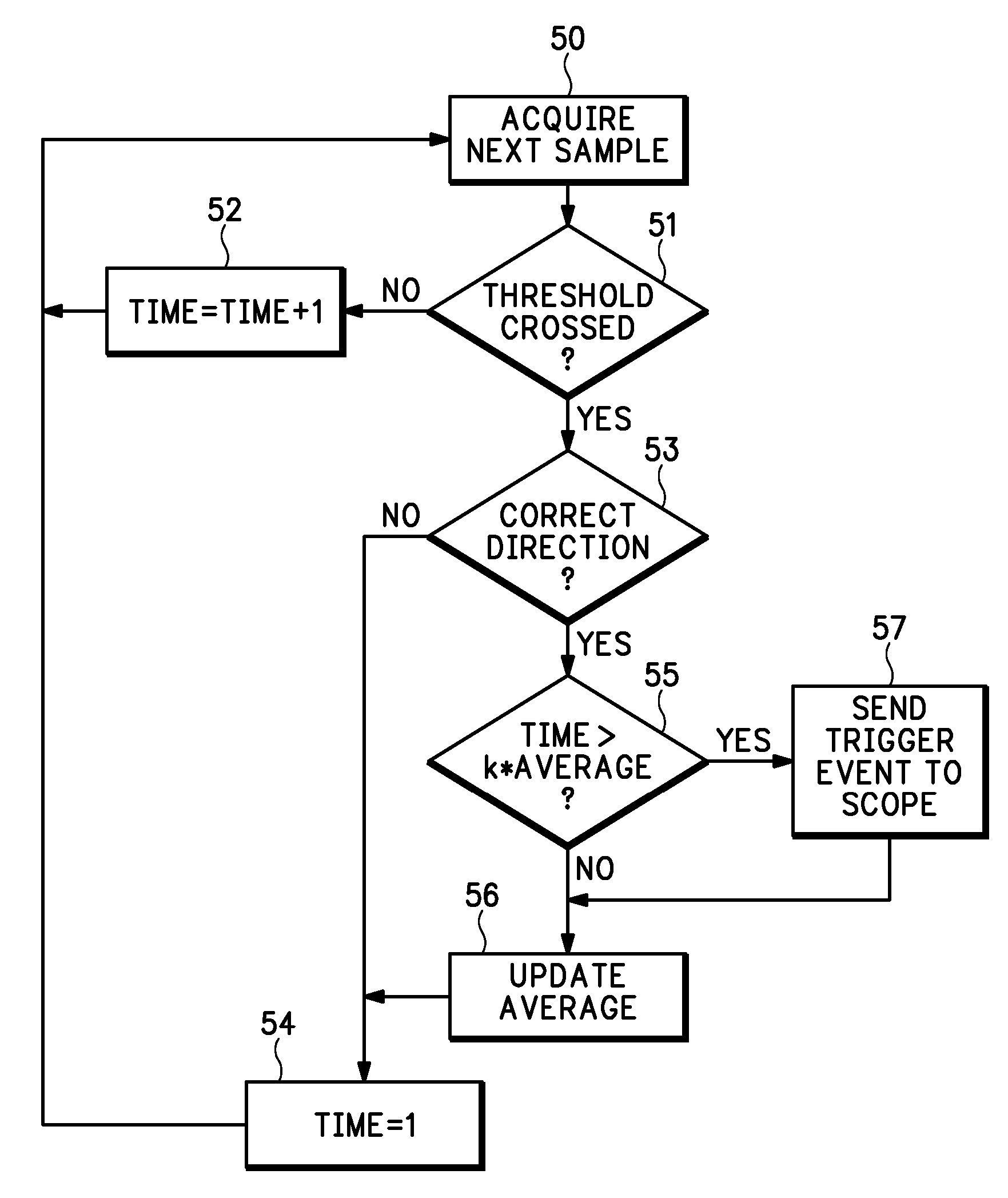
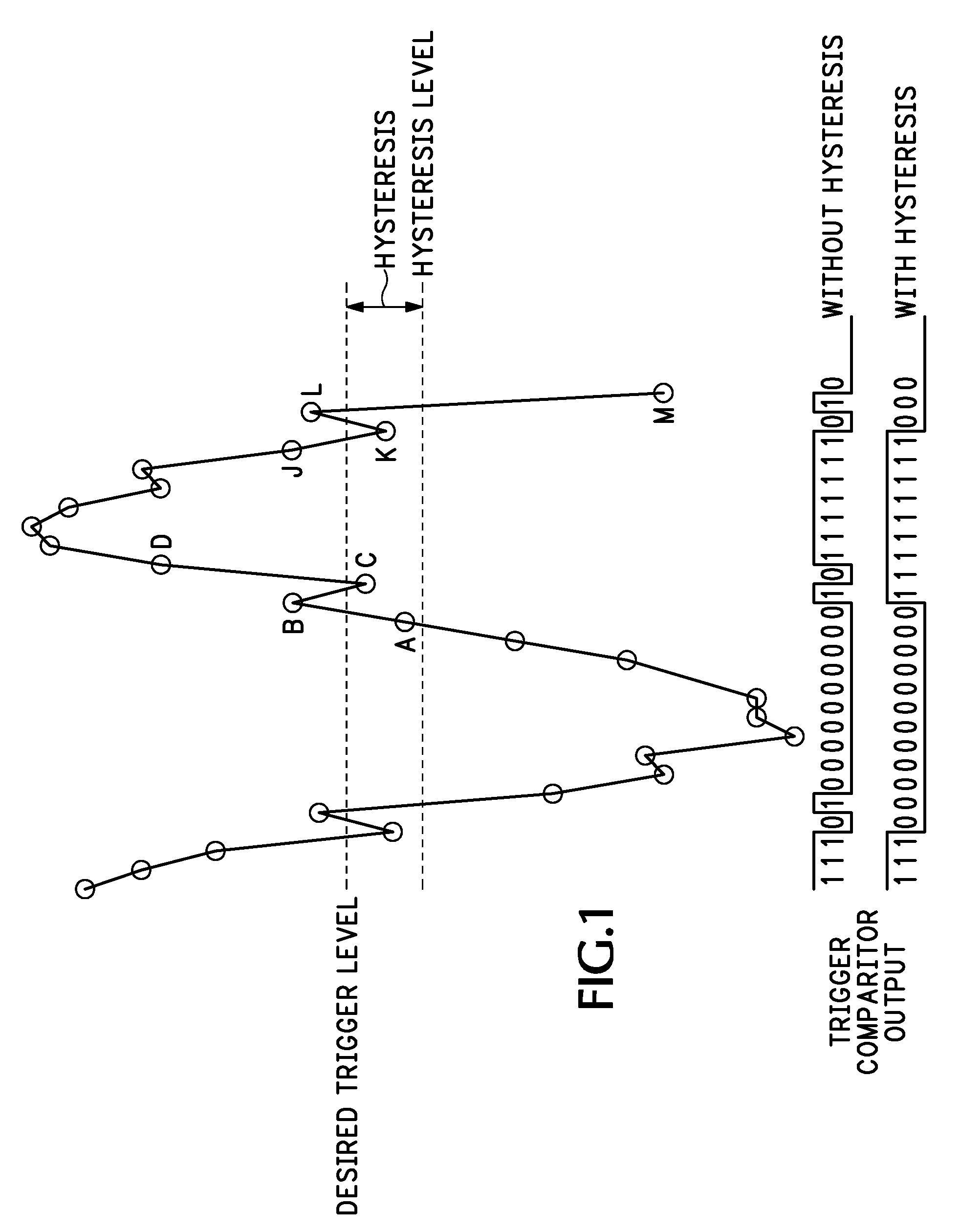
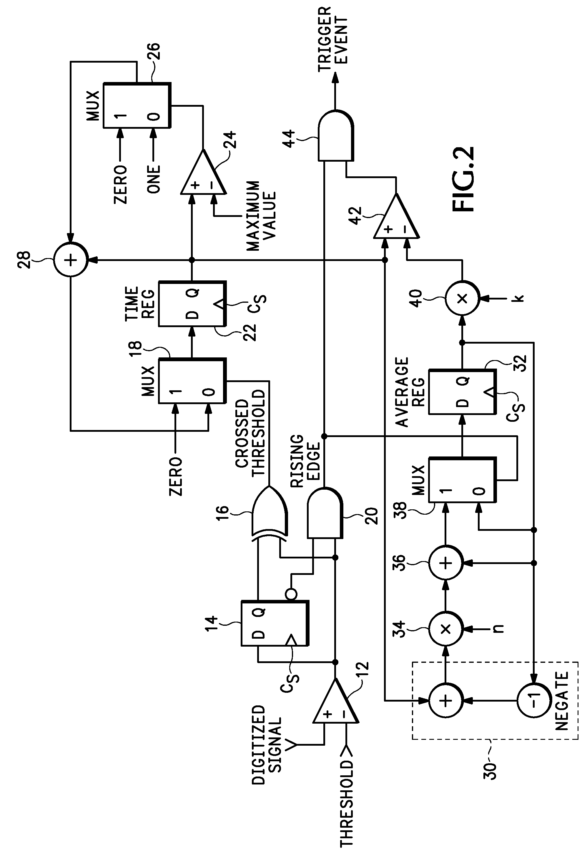
[0016] The present invention has a trigger comparator that does not use hysteresis, so for the digitized signal of FIG. 1 the trigger comparator output observes all rising and falling trigger events, i.e., each crossing of a desired trigger level—only one trigger level is used. Therefore there is a rising trigger event on the transition from point A to point B; a falling trigger event on the transition from point B to point C; a rising trigger event on the transition from point C to point D; a falling trigger event on the transition from point J to point K; a rising trigger event on the transition from point K to point L; and a falling trigger event on the transition from point L to point M. A self-adjusting hold-off trigger circuit, as described below with respect to FIG. 2, measures the time between trigger events and computes an approximation of an average or peak time between trigger events. A trigger event is used for triggering signal acquisition when the time between a curren...


PUM


Abstract

A self-adjusting hold-off trigger circuit and method detects a threshold crossing between consecutive samples of a digitized input signal as edge events, identifies the crossing as a qualified trigger event if the crossing is in a desired direction based upon trigger criteria, and provides a trigger output when the qualified trigger event occurs greater than an approximate average or peak time after a preceding edge event.

Description

CROSS-REFERENCE TO RELATED APPLICATIONS [0001] The current application is a non-provisional application based upon and claiming the filing date under 35 U.S.C. 119(e) of provisional application Ser. No. 60 / 835,562, filed on Aug. 3, 2006, which provisional application is abandoned upon the filing of this non-provisional application.BACKGROUND OF THE INVENTION [0002] The present invention relates to acquisition of an input signal, and more particularly to a self-adjusting hold-off trigger for an acquisition system which is based on approximate time between trigger level crossings by the input signal. [0003] U.S. Pat. No. 7,072,804, issued to Dennis J. Weller on Jul. 4, 2006, discloses a digital trigger circuit having an input filter for producing low and high frequency rejection trigger signals, as well as AC and DC trigger signals, derived from a digitized input signal. One of the four trigger signals is selected by a multiplexer and input to a trigger comparator having an upper trig...

Claims


Application Information

Patent Timeline
IPC IPC(8): H03K5/153
CPCG01R13/0254
Inventor SULLIVAN, STEVEN K.DOBYNS, KENNETH P.GERLACH, PAUL M.
Owner TEKTRONIX INC
Why Eureka
Try Eureka