Radar apparatus

Active Publication Date: 2008-02-07
FURUNO ELECTRIC CO LTD
View PDF10 Cites 18 Cited by
  • Summary
  • Abstract
  • Description
  • Claims
  • Application Information

AI Technical Summary

Benefits of technology

[0009] Accordingly, it is an object of the present invention to provide a radar apparatus with which a user can easily distinguish an actually present object from extr

Problems solved by technology

On the other hand, in the case of white noise or the like, the pla

Method used


Image

  • Radar apparatus
  • Radar apparatus
  • Radar apparatus

Examples


Embodiment Construction

[0028] Following is a description of a radar device according to an embodiment of the present invention with reference to the accompanying drawings. In the present embodiment, a radar device is described by way of example, but the present embodiment is also applicable to a sonar device or the like that detects and displays an object.

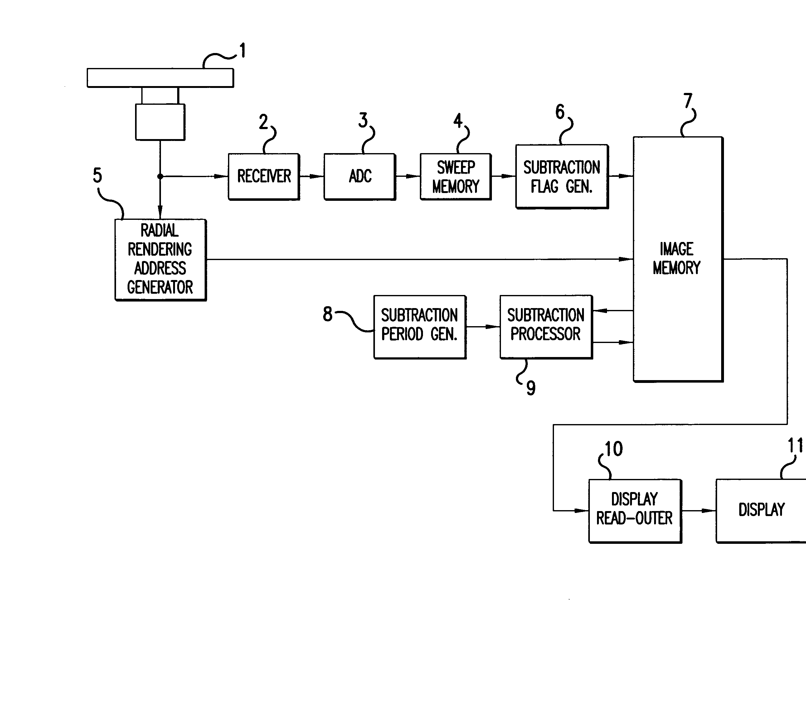
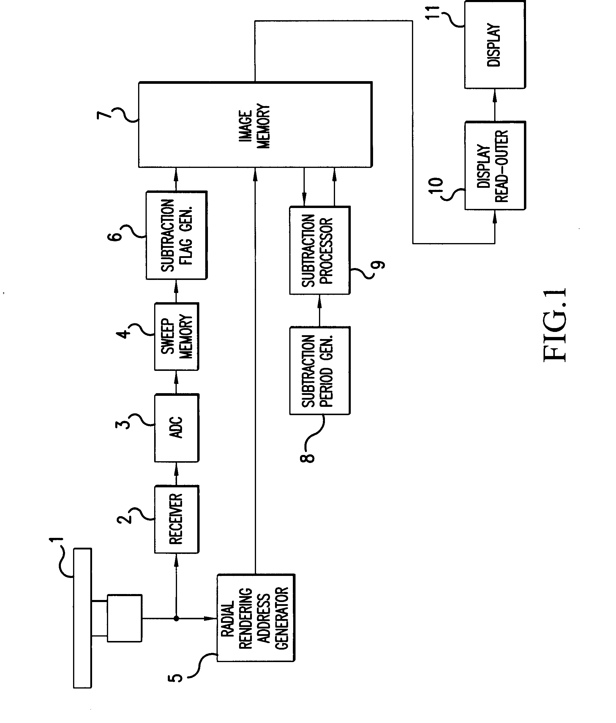
[0029]FIG. 1 is a block diagram showing the principal configuration of a radar device according to this embodiment.

[0030] Radar Antenna 1 of the radar device according to this embodiment, while rotating at a predetermined rotation period in the horizontal plane, emits a pulse-shaped electromagnetic wave during a send-receive period that differs from the rotation period, and also receives, in a polar coordinate system, waves reflected by an object in the surrounding area of the radar device. The Radar Antenna 1 outputs a reception signal to Receiver 2, and outputs sweep angle data to Radial Rendering Address Generator 5.

[0031] Receiver 2 detects and am...


PUM


Abstract

A radar device is realized in which an object and extraneous waves such as radar interference or white noise are distinguished and displayed in different display forms. Subtraction Flag Generator 6 determines the time-wise continuity and the planar consecutiveness of target echo data. The time-wise continuity is an amount that indicates the extent to which significant echo data continued to be present at the same position, and is obtained from the echo data of a past predetermined number of sweep rotations. Planar consecutiveness indicates the extent to which significant echo data is present around target echo data, and is obtained by acquiring in a planar fashion echo data for each of predetermined amounts in a distance direction and a heading direction, centered around the target echo data. When Subtraction Flag Generator 6 detects that there is either of time-wise continuity and planar consecutiveness, Subtraction Flag Generator 6 attaches a subtraction flag “1”. Subtraction Processor 9 sets a low attenuation amount for the data level when the subtraction flag is “1”, and sets a fast attenuation amount when the subtraction flag is “0”.

Description

CROSS REFERENCE OF RELATED APPLICATION [0001] Japanese Patent Application Tokugan No. 2006-196224 Is hereby incorporated by reference. FIELD OF THE INVENTION [0002] The present invention relates to a radar apparatus that converts reception data of a polar coordinate system to image data of a rectangular coordinate system. BACKGROUND ART [0003] Conventionally, in a radar apparatus for detecting objects in all directions from one's own vessel, a reception signal of a polar coordinate system is obtained while rotating a radar antenna at a predetermined period. The radar device converts a reception signal of this polar coordinate system to image data of a rectangular coordinate system and writes the image data to an image memory, and at a predetermined timing reads out image data that has been stored in the image memory. In a display of the radar apparatus, display is performed with the emission intensity and color changed according to the data level of the read-out image data. [0004] I...

Claims


Application Information

Patent Timeline
IPC IPC(8): G01S7/298G01S7/04
CPCG01S7/298G01S7/064
Inventor KOJIMA, TATSUYAFUJIKAWA, TAKUMI
Owner FURUNO ELECTRIC CO LTD
Why Eureka
Try Eureka