Method of manufacturing liquid container, and liquid container
a technology of liquid container and manufacturing method, which is applied in the direction of liquid surface applicators, coatings, printing, etc., can solve the problems of inability to fill the maximum amount of ink for the internal volume of the ink cartridge, and the ink cannot be poured through the outlet part. , to achieve the effect of reducing the time necessary for blocking and being easy to block
- Summary
- Abstract
- Description
- Claims
- Application Information
AI Technical Summary
Benefits of technology
Problems solved by technology
Method used
Image
Examples
first embodiment
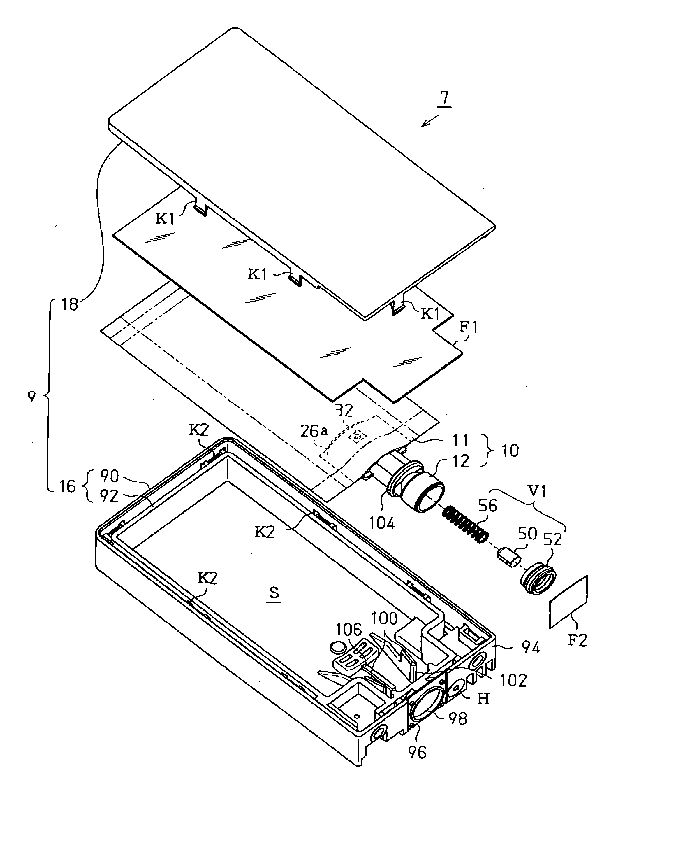
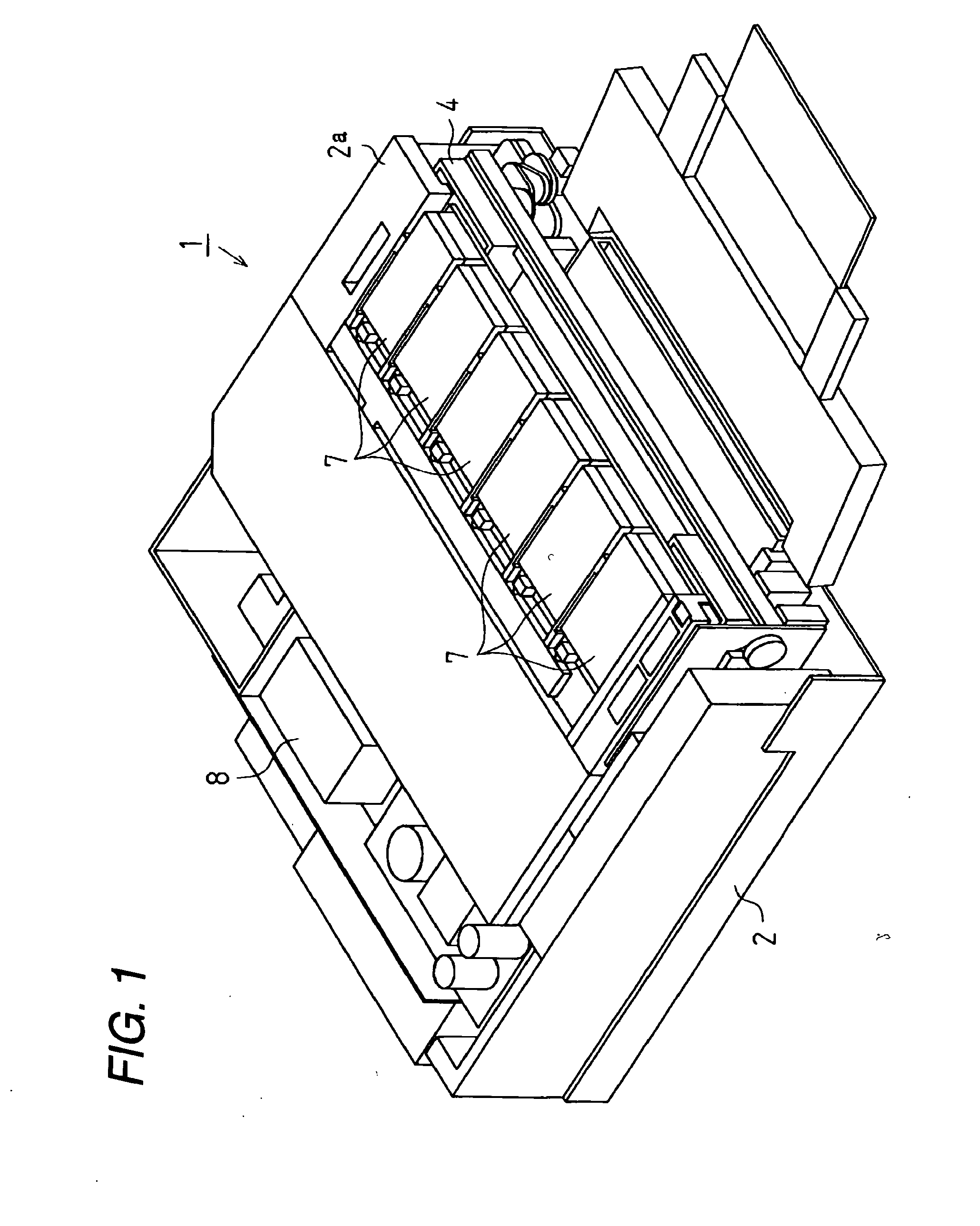
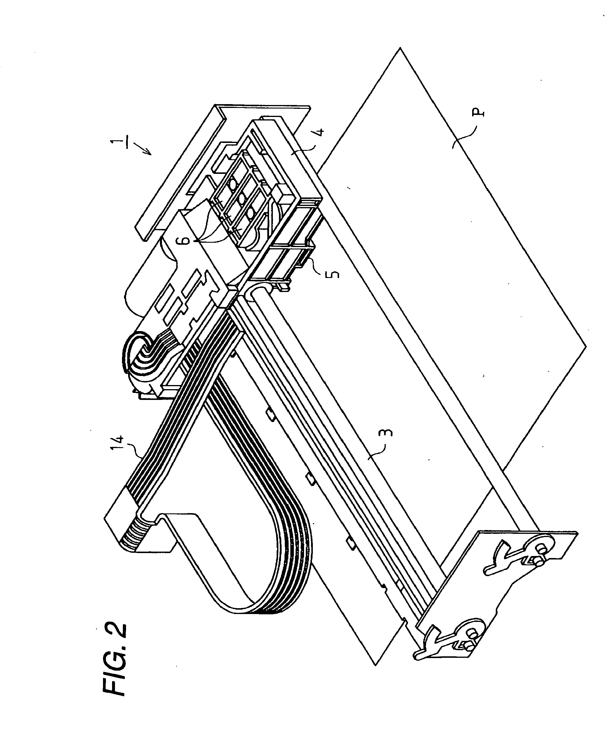
[0033] A first embodiment of the invention will be described below with reference to FIGS. 1 to 6. FIG. 1 is a perspective view of an ink jet type recording apparatus (hereinafter referred to simply as a printer 1) used as a liquid jet apparatus in the embodiment, FIG. 2 is a main portion perspective view of the printer 1, and FIG. 3 is an exploded perspective view of an ink cartridge provided for the printer 1.
[0034] As shown in FIG. 1, the printer 1 in the embodiment is an ink jet type, and includes a frame 2. Inside the frame 2, as shown in FIG. 2, a guide member 3, a carriage 4, a recording head 5, and a valve unit 6 are provided. Further, the printer 1 is provided, as shown in FIG. 1, with an ink cartridge 7 as a liquid container, and an air pressure pump 8. The frame 2 is a box body formed generally in the shape of a rectangular parallelepiped, and has a cartridge holder 2a on its front surface.
[0035] The guide member 3, as shown in FIG. 2, is formed in the shape of a rod, a...
second embodiment
[0079] Next, a second embodiment of the invention will be described with reference to FIGS. 7 and 8. This embodiment is characterized by a blocking method of the bypass flowing passage 32 of the ink pack 10 described in the first embodiment. In the following description, the same parts as those in the first embodiment are denoted by the same reference characters, and their detailed descriptions are omitted.
[0080] As shown in FIG. 7, in the ink pack 10 before the ink is filled, a blocking means, that is, a blocking member 110 as a stopper is coupled to the outlet part 12 rotatably in relation to the opening part of the bypass flowing passage 32. The blocking member 110 is coupled through a coupling part 110a to the outlet part 12, and rotates about the coupling part 110a. The blocking member 110 is usually arranged in a position where the bypass flowing passage 32 is opened. When the blocking member 110 is pressed from the upside, it rotates about the coupling part 110a, and fitted ...
PUM
 Abstract
Description
Claims
Application Information
 - R&D
- Intellectual Property
- Life Sciences
- Materials
- Tech Scout
- Unparalleled Data Quality
- Higher Quality Content
- 60% Fewer Hallucinations
Browse by: Latest US Patents, China's latest patents, Technical Efficacy Thesaurus, Application Domain, Technology Topic, Popular Technical Reports.
© 2025 PatSnap. All rights reserved.Legal|Privacy policy|Modern Slavery Act Transparency Statement|Sitemap|About US| Contact US: help@patsnap.com


