Optical assemblies for free-space optical propagation between waveguide(s) and/or fiber(s)

a technology of optical propagation and optical assembly, applied in the field of free-space optical power transfer, can solve the problems of large transverse dimensions of such components that cannot yet be implemented within a waveguide or optical fiber, inability to provide transverse confinement or guiding of propagating optical power, and high cost and time-consuming active alignment procedures

Inactive Publication Date: 2008-02-07
HOYA USA
View PDF15 Cites 18 Cited by
  • Summary
  • Abstract
  • Description
  • Claims
  • Application Information

AI Technical Summary

Problems solved by technology

Many optical components cannot yet be implemented within a waveguide or optical fiber, but require so-called “free-space” propagation of optical power through the component.
The transverse dimensions of such components are typically too large to provide transverse confinement or guiding of the propagating optical power, which will converge and/or diverge as it propagates through the component.
Achieving alignment

Method used


Image

  • Optical assemblies for free-space optical propagation between waveguide(s) and/or fiber(s)
  • Optical assemblies for free-space optical propagation between waveguide(s) and/or fiber(s)
  • Optical assemblies for free-space optical propagation between waveguide(s) and/or fiber(s)

Examples


Embodiment Construction

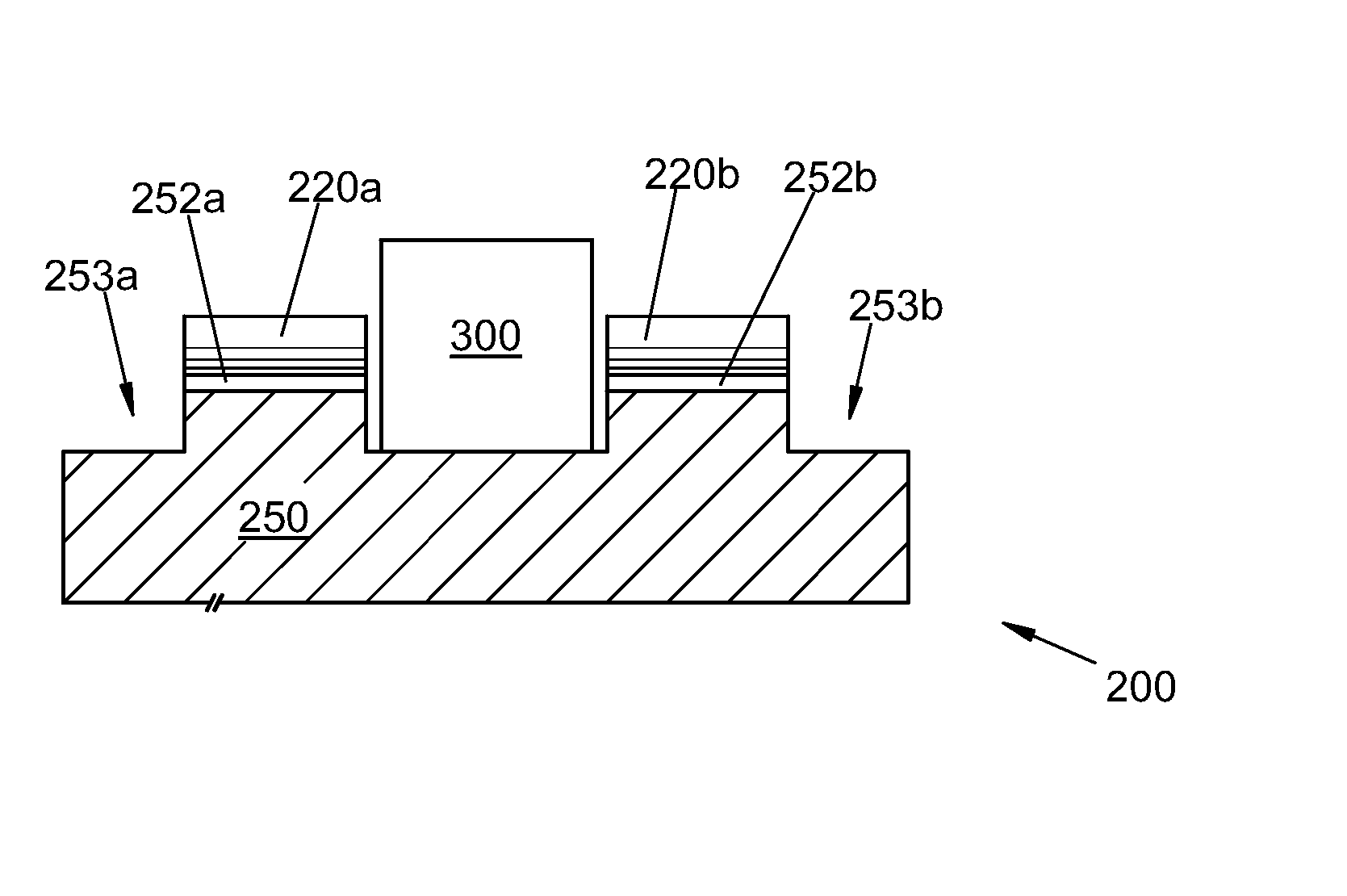
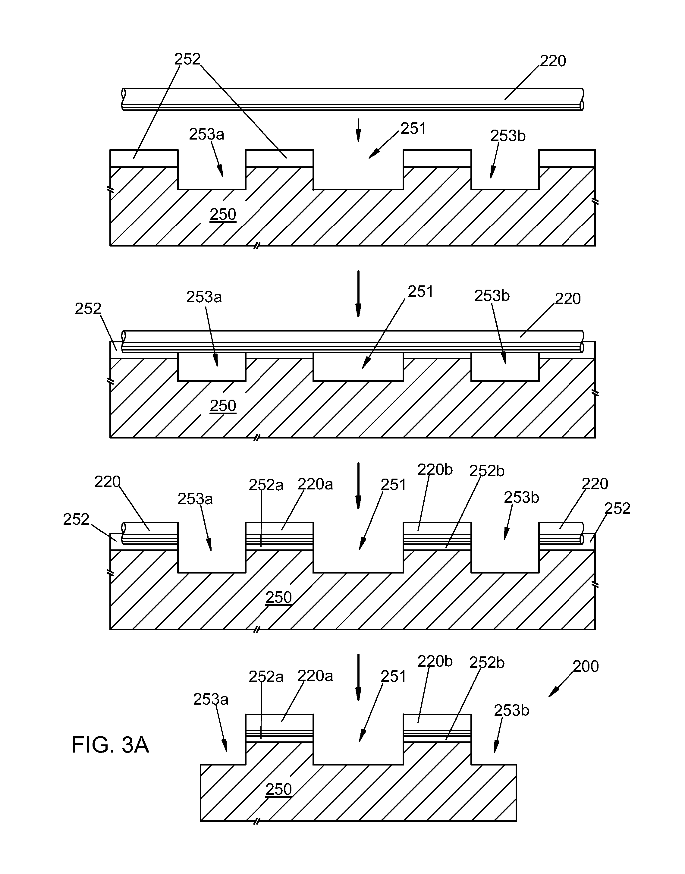
[0046] Exemplary fabrication / assembly sequences are illustrated in FIGS. 3A-3F, each for producing an exemplary dual-lens optical assembly 200. In each sequence, a substrate 250 is provided with an elongated groove 252, typically a V-groove, using spatially selective material processing. For simultaneous fabrication of multiple assemblies on a wafer scale, multiple substantially parallel grooves 252 may be provided on substrate 250 (FIGS. 3C and 3F). In a first exemplary sequence (FIGS. 3A-3C), recessed areas 251 and 253a / 253b are formed on substrate 250 using spatially selective material processing. These recessed areas divide the V-groove(s) 252. Multiple recessed areas 251 / 253a / 253b may be formed dividing multiple V-grooves 252 each into multiple segments as in FIG. 3C, for a fabrication / assembly sequence implemented on a wafer scale. Separate recessed areas may be formed (not shown), or groups of recessed areas may be formed together as slots or grooves running across the substr...


PUM


Abstract

An optical apparatus is made by mounting segments of a GRIN optical medium on a substrate in at least one groove thereon. The GRIN segments are longitudinally spaced apart from one another on the substrate, and are arranged so that a free-space optical beam received through the distal end face of the first GRIN segment is transmitted through the proximal end face of the first GRIN segment, propagates to the proximal end face of the second GRIN segment, is received through the proximal end face of the second GRIN segment, and is transmitted as a free-space optical beam through the distal end face of the second GRIN segment. The GRIN segments can be formed by division of a single GRIN optical medium mounted on the substrate

Description

BENEFIT CLAIMS TO RELATED APPLICATIONS [0001] This application is a divisional of U.S. non-provisional application Ser. No. 10 / 652,955 filed Aug. 29, 2003, which in turn claims benefit of U.S. provisional App. Nos. 60 / 413,986 filed Sep. 25, 2002, 60 / 455,712 filed Mar. 17, 2003, and 60 / 466,799 filed Apr. 29, 2003, each of said applications being hereby incorporated by reference as if fully set forth herein. BACKGROUND [0002] The field of the present invention relates to free-space optical power transfer. In particular, optical assemblies for free-space optical propagation between waveguide(s) and / or fiber(s), and fabrication methods therefor, are disclosed herein. [0003] Many optical components cannot yet be implemented within a waveguide or optical fiber, but require so-called “free-space” propagation of optical power through the component. The transverse dimensions of such components are typically too large to provide transverse confinement or guiding of the propagating optical pow...

Claims


Application Information

Patent Timeline
IPC IPC(8): G02B6/26G02B6/32G02B6/36
CPCG02B6/2746G02B6/30G02B6/3692G02B6/3636G02B6/3652G02B6/32
Inventor BLAUVELT, HENRY A.VERNOOY, DAVID W.PASLASKI, JOEL S.
Owner HOYA USA
Why Eureka
Try Eureka