
Illumination system for dental applications

a technology of dental applications and a slitting system, applied in the field of dental slitting systems, can solve the problems of tooth decay, cavities or other damage, and the time of dental slitting and bleaching is much longer

Inactive Publication Date: 2008-02-07
DISCUS DENTAL LLC
View PDF31 Cites 85 Cited by
  • Summary
  • Abstract
  • Description
  • Claims
  • Application Information

AI Technical Summary

Benefits of technology

[0012] The present invention is directed to a system an apparatus and method for dental whitening, curing, therapeutic treatment, or imaging that offers freedom of movement for the patient during the dental process.
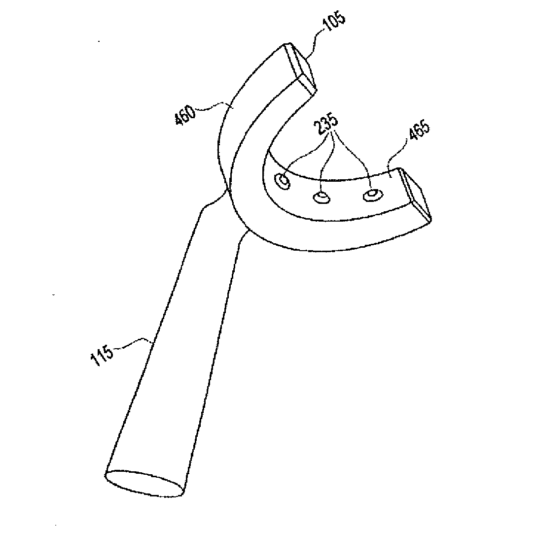
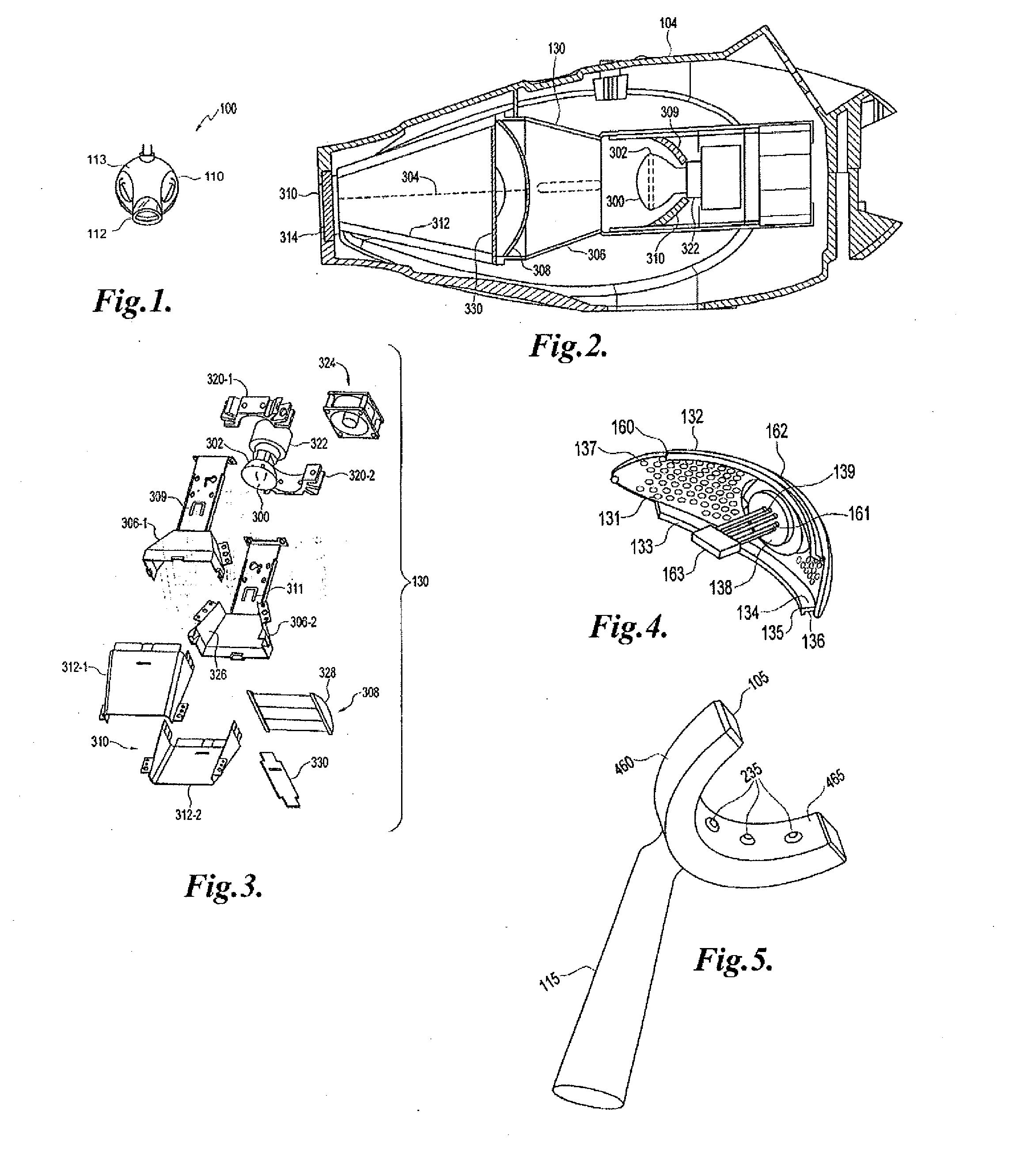
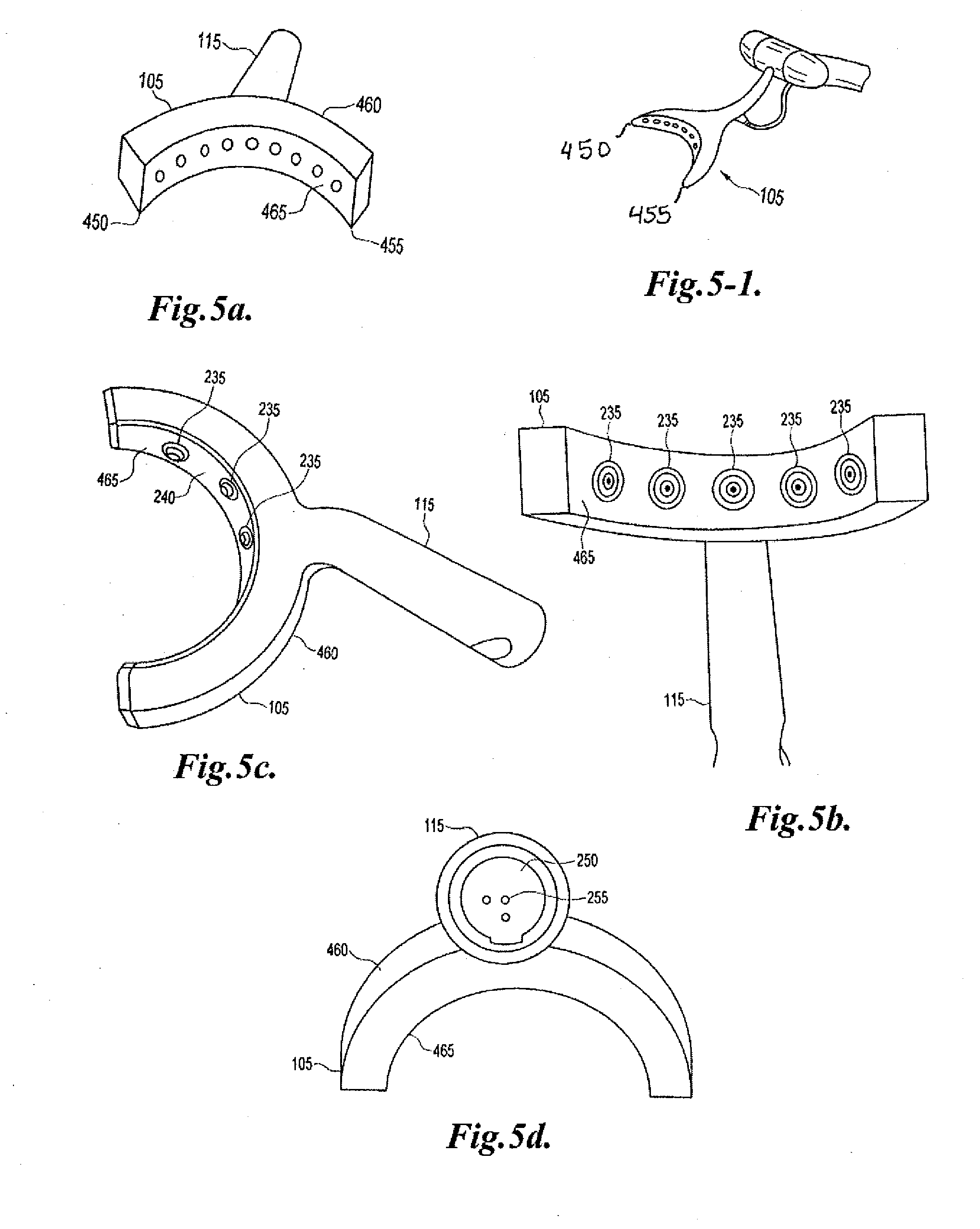
[0013] In one aspect, the present invention is directed to an alignment system to facilitate faster patient set up and optimal results. In another aspect, the present invention is directed to efficacy of procedure with minimal disruption. In one embodiment the alignment system includes an apparatus for positioning a dental illumination device relative to a subject, including a lamp system and reference device for engaging the lamp system for positioning the lamp system at a predetermined distance from the target. The lamp system includes a lamp head. The reference device includes a light distributor. Examples of the light distributor includes a light pipe, a light guide; a mouthpiece, a tongue illuminator, an illumination plate, a dental tray, a dental floss, or combinations thereof.

Problems solved by technology

In addition to staining, tooth decay, resulting in cavities or other damages can also result.
Unlike dental curing and imaging processes, which are generally relatively fast processes, dental bleaching takes a much longer time, sometimes amounting to more than an hour per office visit.
On the other hand, dental restoration is often an unwelcome experience.
The wide range of dentist's chair positions can make this alignment difficult.
Also, an efficient lamp requires less energy to run than an inefficient lamp.

Method used


Image

  • Illumination system for dental applications
  • Illumination system for dental applications
  • Illumination system for dental applications

Examples


example 1

[0264] Individual emitters were characterized in terms of the angular distribution of their radiant emissions. Royal Blue emitters may provide more radio-metric power than Blue emitters, for example, as shown in FIG. 25a. It is possible that some emitters may provide other radiometric power, though on average, an array may function as desired.

example 2

[0265] Following completion of the characterization of individual emitters, a calculation for an emitter array geometry that could deliver the target optical power throughout most of the target zone of use (Zone 1) was carried out.

[0266] The prototype of an 18-emitter array geometry which could deliver the target radiometric power (130 mW / cm″2) through out most of Zone 1 using an IDEO optical analysis tool was constructed and radiometric power delivered across the surface of the teeth was measured. As shown by the graph in FIG. 25b, the prototype array delivered the target optical power throughout much of Zone 1. FIG. 25b shows a plot of radiometric power as a function of position along tooth surface. These results from the full emitter array optical measurements were encouraging, with much of Zone 1 falling within the target power range. These results gave positive results for an effective teeth whitening device utilizing an array of approximately 20 LuxeonV emitters.

[0267] Exper...

experiment 4

[0272]FIG. 31 shows a block diagram of a top level Electrical System for the illumination product and a discussion of the primary novel issues, such as the design of appropriate driver circuitry for an array of LuxeonV emitters.

[0273] Electrical Architecture

I. The hardware design for the prototype included the following elements:

[0274] 1. Keypad—A 14 pad keypad was used to duplicate the keypad functionality of the present system.

[0275] 2. Speaker

[0276] An exiting speaker and speaker circuitry, such as that used in BriteSmile® 3000PB was used and the details are presented below.

[0277] 3. Main controller

[0278] The main controller and associated circuitry of BriteSmile® 3000 PB was used in the prototype. LCD—The LCD and LCD interface was also the same as used in BriteSmile® 3000 PB. Interface to LED controller—The interface to the LED controller was a serial port interface. LED driver control—There were 18 high power LEDs to operate, as exemplified. These LEDs were driven eithe...


PUM


Abstract

A dental illumination system includes an adjustable lamp head including a source of radiation, which may including IR, visible, and / or UV, is provided with an adjustable mounting device adapted for mounting in such a manner that offers freedom of movement for the patient undergoing the procedure, for example, whitening, so that radiation may be directed at the tooth or teeth. In some embodiments, the lamp head includes a housing and a spacer having formations that is adapted to removably mechanically couple the lamp head to a reference device, again having formations, for facilitating illumination of a tooth by a light source contained within the lamp head. The spacer and lamp head may be formed integrally. If formed separately, both the lamp head and the spacer may include formations.

Description

CROSS-REFERENCE TO RELATED APPLICATIONS [0001] This application is a continuation-in-part of U.S. patent application Ser. No. 11 / 173,839, filed Jun. 30, 2005, which claims priority to provisional patent application Ser. Nos. 60 / 641,462, filed Jan. 4, 2005, entitled “Boom Hinge For A Dental Lamp”; 60 / 647,723, filed Jan. 26, 2005, entitled “Boom Hinge For A Dental Lamp”; entitled “Lamp For Dentistry Applications”; 60 / 647,580, filed Jan. 26, 2005, entitled “Light Guide For Dental Whitening Lamp”; 60 / 641,461, filed Jan. 4, 2005, entitled “Support Structure For A Dental Lamp”; 60 / 641,468, filed Jan. 4, 2005, entitled “Light Guide For A Dental Whitening Lamp”; 60 / 647,593, filed Jan. 26, 2005, entitled “Support Structure For A Dental Lamp”; 60 / 604,577, filed Aug. 25, 2004, entitled “Lip Retractors”; and 60 / 641,469, filed Jan. 4, 2005, entitled “Lamp For Dentistry Applications”; and claims the benefit of U.S. provisional patent applications Ser. Nos. 60 / 814,242, filed Jun. 15, 2006, entitle...

Claims


Application Information

Patent Timeline
Patent Type & Authority Applications(United States)
IPC IPC(8): A61C3/00
CPCA61B5/0088A61C1/088A61N2005/0606A61C19/066A61C19/004
Inventor HAYMAN, ROBERTQUAN, CHRISTOPHER
Owner DISCUS DENTAL LLC
Learn More