Prostatic stent placement device

a technology of stents and implants, which is applied in the field of catheters and stents, can solve the problem that devices cannot be continuously inserted into active patients, and achieve the effect of improving the stability and stability of the patien

Inactive Publication Date: 2008-02-07
VANCE PROD INC D B A COOK UROLOGICAL INC
View PDF43 Cites 30 Cited by
  • Summary
  • Abstract
  • Description
  • Claims
  • Application Information

AI Technical Summary

Problems solved by technology

While the use of a Foley catheter and The Spanner™ have been successfully used to promote urine flow through the urinary tract after urological pr

Method used


Image

  • Prostatic stent placement device
  • Prostatic stent placement device
  • Prostatic stent placement device

Examples


second embodiment

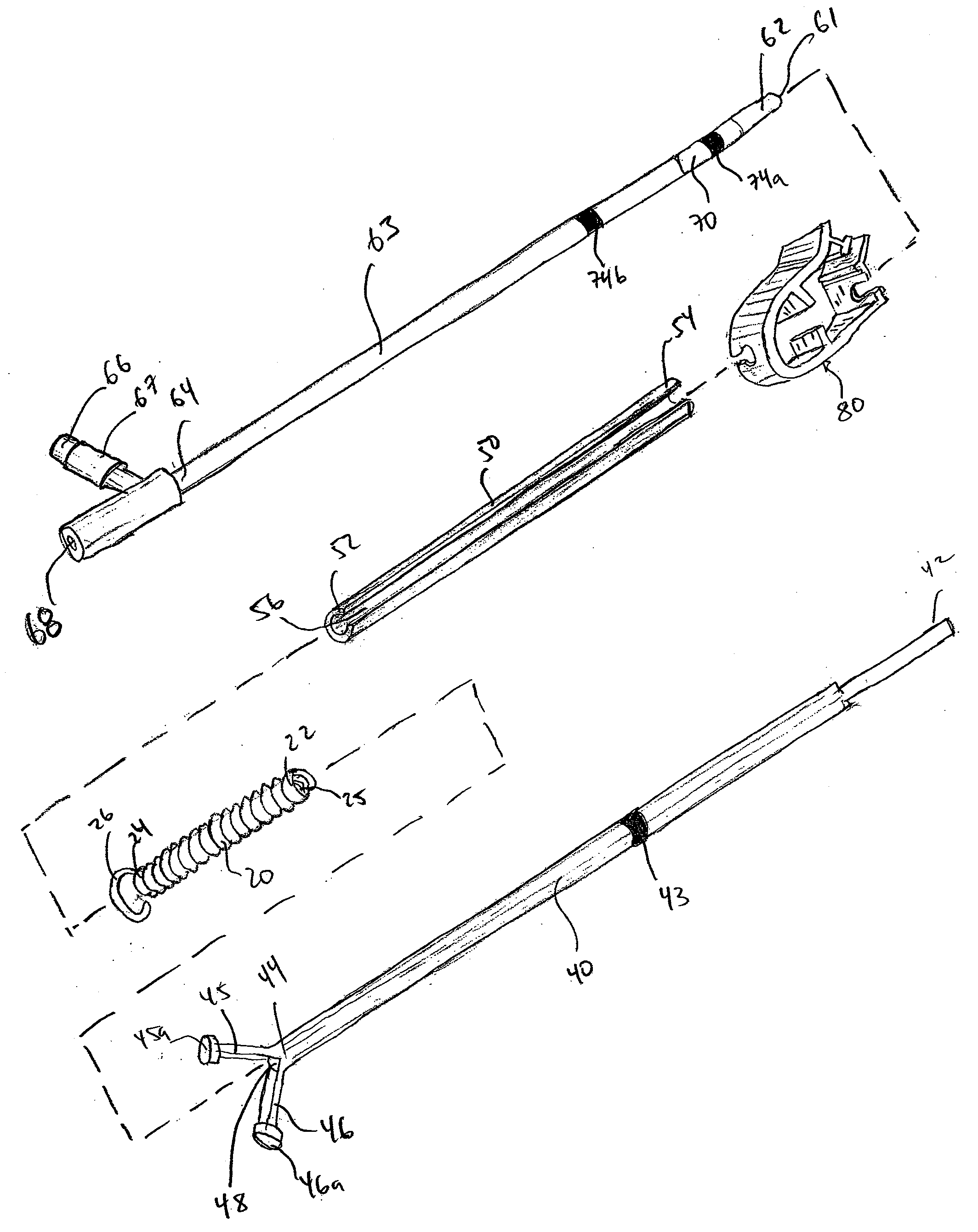
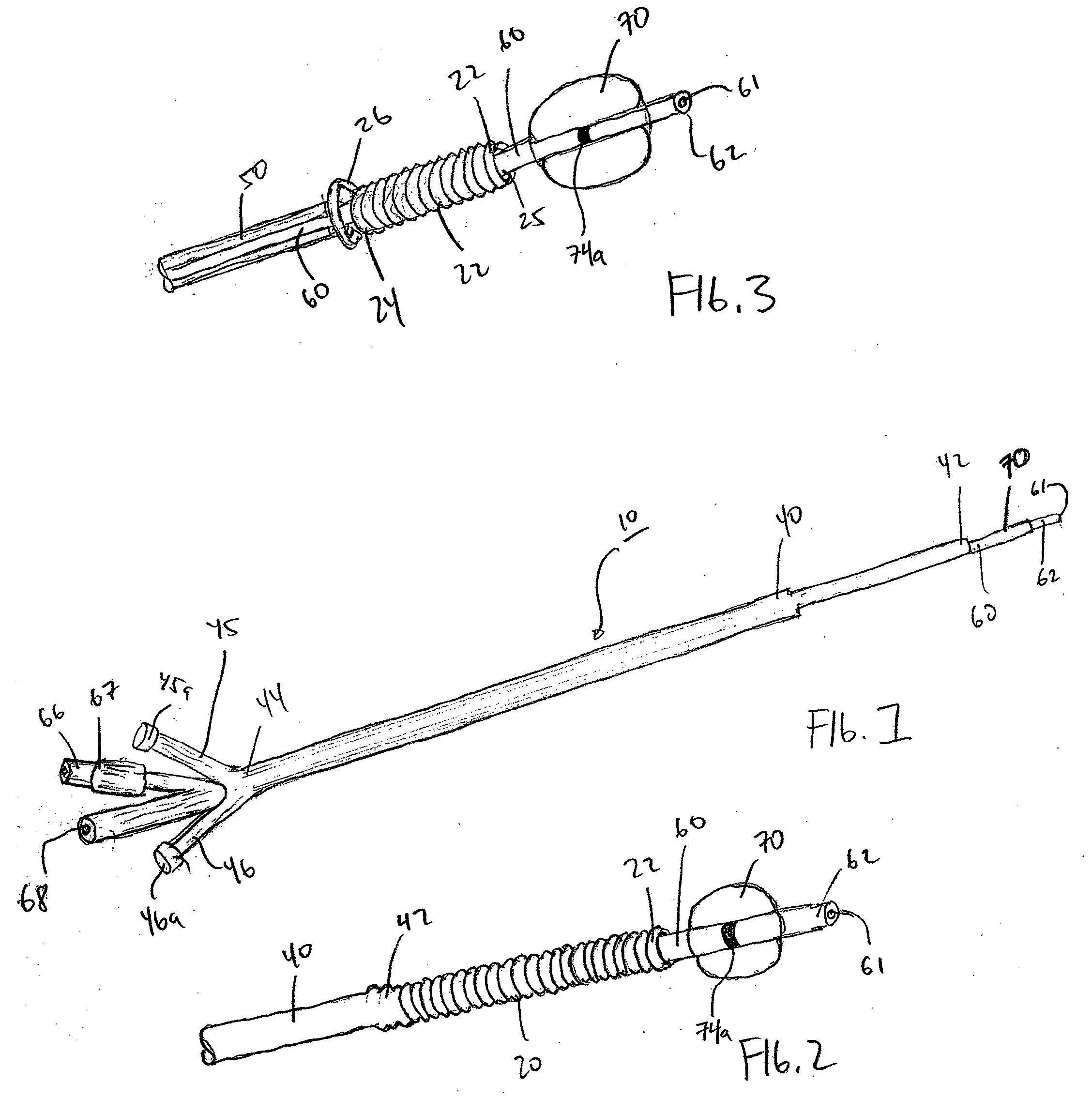
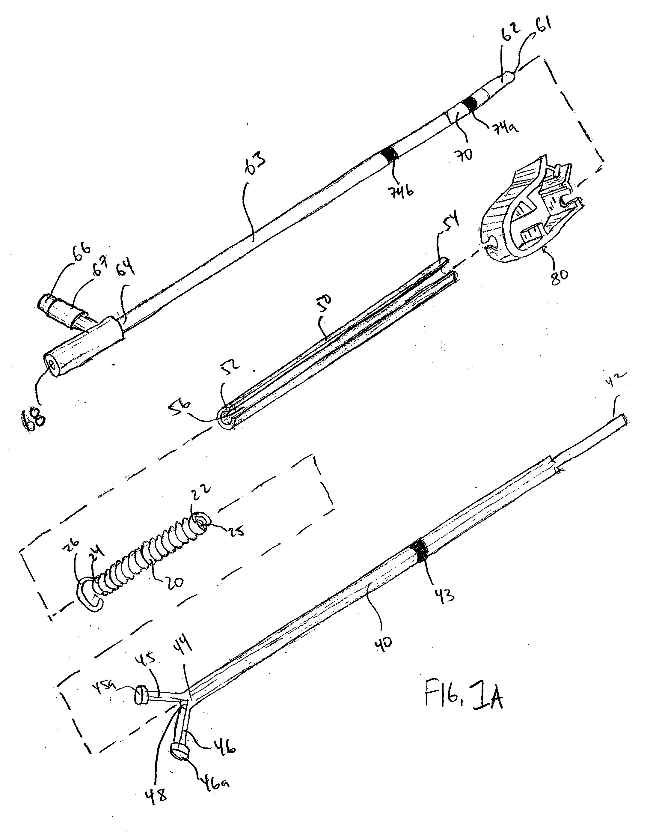
[0067] stent positioning device 100 is provided and shown in FIGS. 11 and 12. This embodiment can be used in the same situations and medical circumstances as the embodiment described above. This embodiment includes many of the same components discussed above, including stent 20, stent pusher 30, and outer sheath 40. This embodiment additionally includes an alternate balloon catheter 160 that is shown in FIG. 11. Balloon catheter 160 includes a distal end 162 and a proximal end 164.

first embodiment

[0068] Balloon catheter 160 includes distal balloon 170 located at distal end 162 and proximal balloon 172 located proximally of distal balloon 170 along the longitudinal axis of balloon catheter 160. In some embodiments, a radiopaque marker 174 is provided rearwardly of proximal balloon 172 along the length of balloon catheter 160, or in another convenient location on balloon catheter 160. This radiopaque marker 174 is formed and detected in the same manner as discussed above in the Balloon catheter 160 additionally includes two inflation / deflation ports, a first inflation / deflation port 166 that is connected to distal balloon 170 through an inflation lumen (not shown) located within the balloon catheter 160 and a second inflation / deflation port 167 that is connected to proximal balloon 172 through a second inflation lumen (not shown) or vice-versa. Each of the first and the second inflation / deflation ports 166, 167 may include check valves 166a, 167a in some embodiments that prev...


PUM


Abstract

The present invention provides a method and apparatus for maintaining urine flow during and after urological procedures. The invention includes a stent for long term insertion into a patient's urinary tract, a Foley catheter which is used to support the stent during placement, a positioning shaft which is used to position the stent with respect to the catheter, and a protective sheath that retains these components in place during insertion of the stent. Alternatively, a Foley catheter with two balloons may be used in place of the stent positioner, with the stent being accurately positioned with one of the two balloons being surrounded by the stent.

Description

CROSS REFERENCE TO RELATED APPLICATIONS [0001] This application claims priority to U.S. Provisional Application No. 60 / 791,591, filed on Apr. 12, 2006, and is hereby fully incorporated by reference herein. This application is additionally a continuation-in-part of U.S. application Ser. No. 10 / 899,807, filed on Jul. 27, 2004, which claims benefit of Provisional Application No. 60 / 491,781, filed on Aug. 1, 2003, both of which are hereby fully incorporated by reference herein.FIELD OF THE INVENTION [0002] The present invention relates to the field of catheters and stents for use in a medical situation. BACKGROUND OF THE INVENTION [0003] Several methods and apparatuses for maintaining urethral patency are known for use during and after urological treatments. For example, it is known in the art to use a Foley catheter that is positioned within the urethra with a balloon on the distal end that extends into the bladder with the catheter including a lumen to allow for urine flow through the...

Claims


Application Information

Patent Timeline
IPC IPC(8): A61F2/82A61F2/84
CPCA61F2/958
Inventor BLITZ, BENJAMIN T.WARD, JOHN H.
Owner VANCE PROD INC D B A COOK UROLOGICAL INC
Why Eureka
Try Eureka