
Vehicle controller and method of controlling a vehicle

a technology of vehicle controller and vehicle, applied in the direction of process and machine control, braking system, instruments, etc., can solve the problems of sudden change of drive power, discontinuity of drive power,

Inactive Publication Date: 2008-02-07
TOYOTA JIDOSHA KK
View PDF4 Cites 5 Cited by
  • Summary
  • Abstract
  • Description
  • Claims
  • Application Information

AI Technical Summary

Benefits of technology

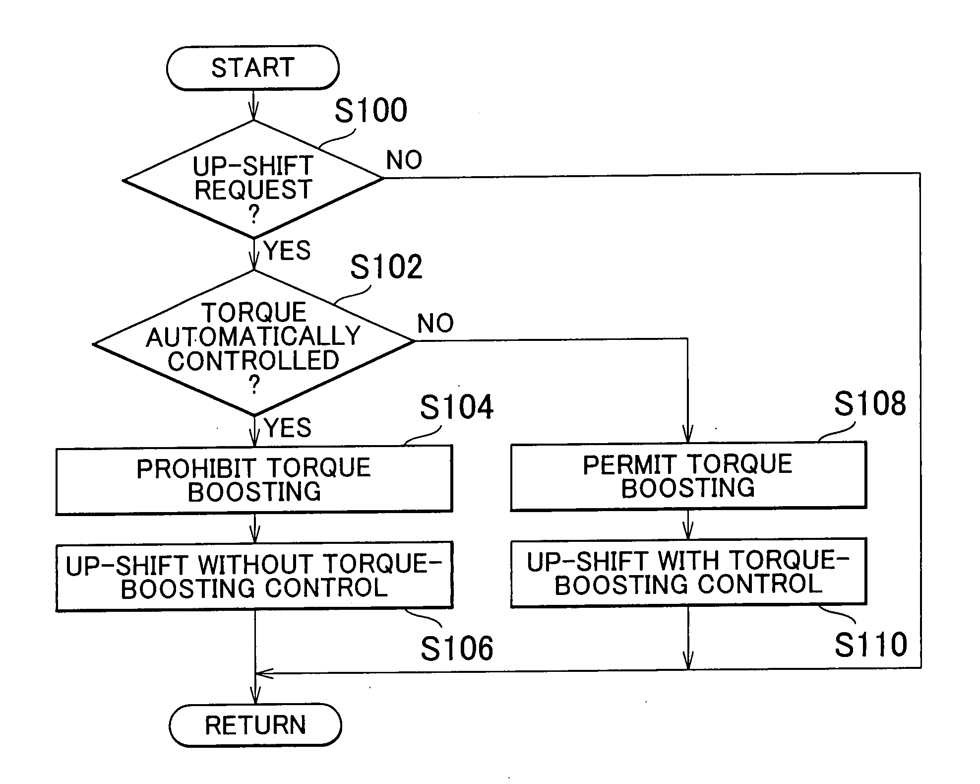
[0011]According to the vehicle controller the first aspect, when the torque of the power source is automatically controlled independently of the demanded output amount demanded by the driver (for example, the accelerator operation amount), torque boosting is prohibited during the torque phase. By doing this, it is possible to suppress sudden changes in the torque output from the power source from the automatically controlled torque to the torque referenced to the demanded torque. For this reason, it is possible to suppress a sudden change of the drive power. As a result, it is possible to provide a controller of a vehicle that suppresses the generation of a torque shock when the gear shifting.
[0018]A second aspect of the present invention relates to a method of controlling a vehicle. The method controls a vehicle equipped with a power source and an automatic transmission, connected to the power source, that establishes a plurality of gear steps with different gear ratios by selectively engaging a plurality of friction engaging elements. The vehicle is controlled by increasing the torque of the power source during a torque phase of the up-shift when the automatic transmission is up-shifted, and prohibiting an increase of the torque during the torque phase when the torque output of the power source is automatically controlled, independently of the output amount demanded by a driver.

Problems solved by technology

By boosting torque during the torque phase, if torque is boosted based on a torque demanded in response to the demanded output amount demanded by the driver (for example, by an accelerator operation amount), there is a problem of a discontinuity in drive power because of the torque boosting.
As a result, the ultimately controlled torque of the power source becomes discontinuous, resulting in a sudden change in the drive power.

Method used


Image

  • Vehicle controller and method of controlling a vehicle
  • Vehicle controller and method of controlling a vehicle
  • Vehicle controller and method of controlling a vehicle

Examples


Embodiment Construction

[0029]Example embodiments of the present invention are described below with reference made to the accompanying drawings. In the description to follow, the same reference numerals and names are assigned to the same elements, and previously described elements are not repeatedly described.

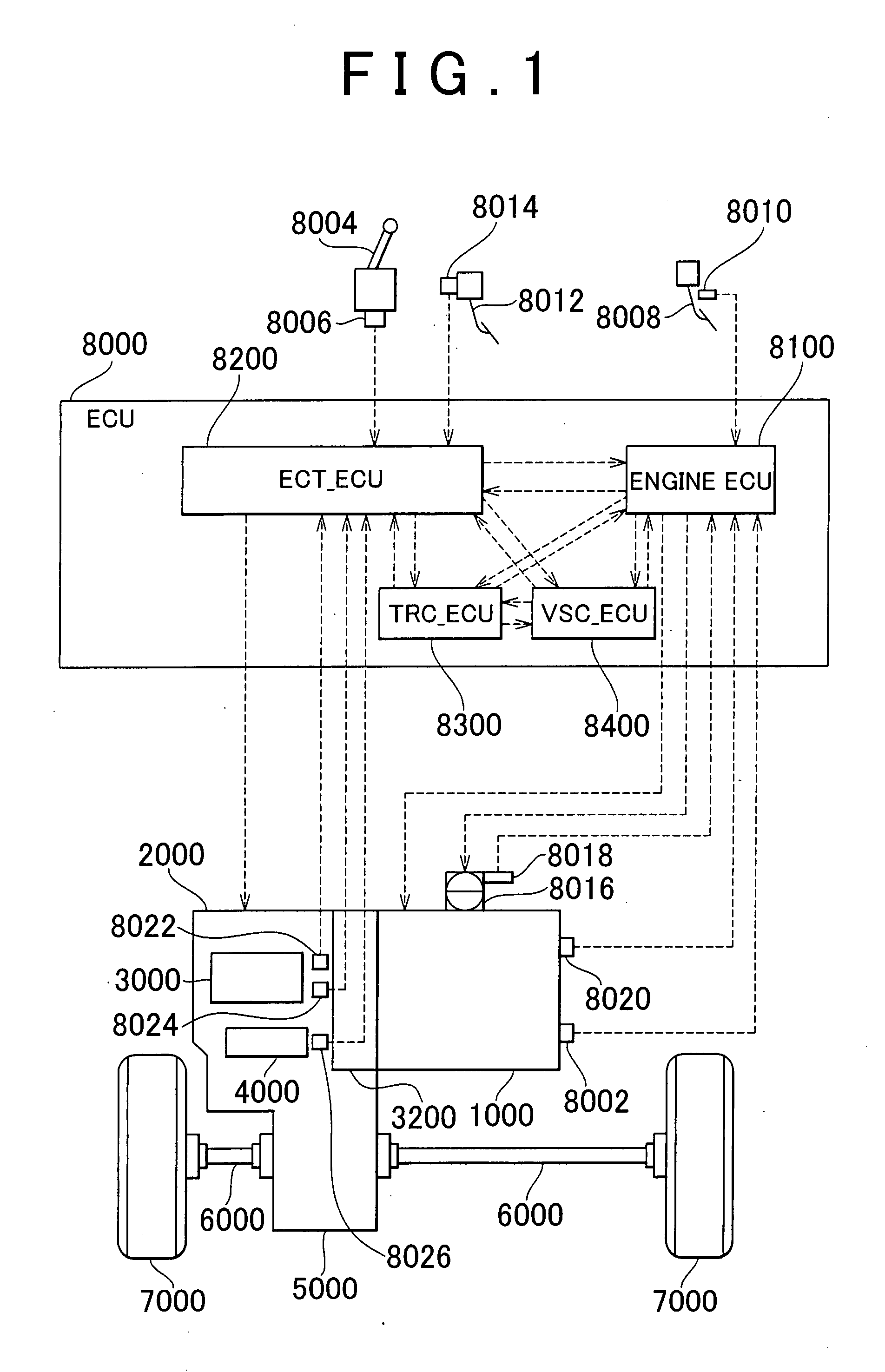
[0030]Referring to FIG. 1, a vehicle in which a controller according to an embodiment of the present invention will be described. This vehicle is a front-engine, front-drive (FF) vehicle, but may be a different type of vehicle.

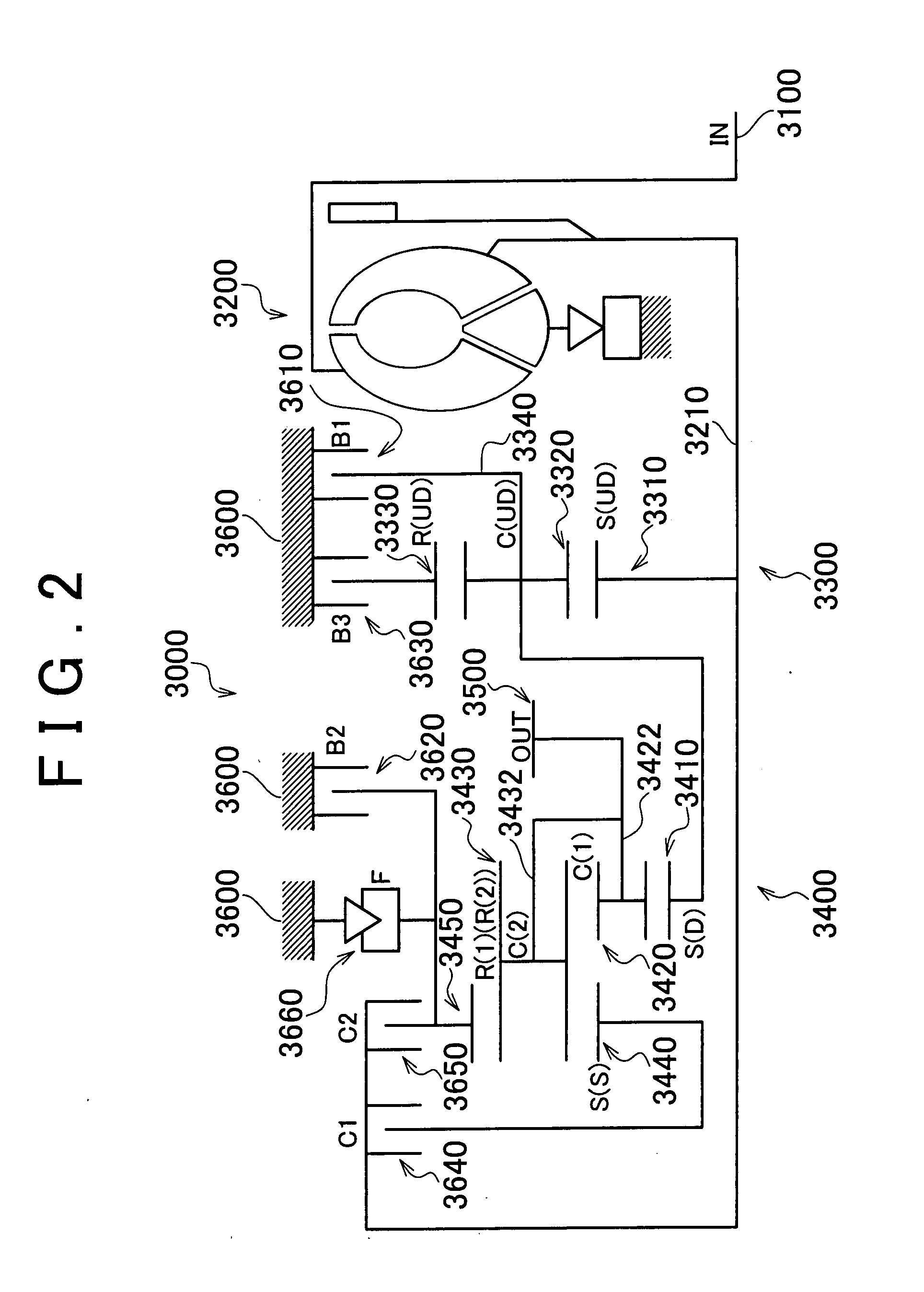
[0031]The vehicle shown in FIG. 1 includes an engine 1000, an automatic transmission 2000, a planetary gear unit 3000 forming part of the automatic transmission 2000, a hydraulic circuit 4000 forming part of the automatic transmission 2000, a differential gear 5000, a drive shaft 6000, front wheels 7000, and an ECU 8000 (electronic control unit). The controller according to an embodiment of the present invention is implemented, for example, by executing a program stored in a ROM...


PUM


Abstract

When it is determined that the torque output from a power source is being automatically controlled, an ECU prohibits torque-boosting control of the power source during the torque phase when up-shifting, and performs up-shifting without performing torque-boosting control. In performing torque-boosting control, the driver demanded torque in response to the accelerator operation amount is used as the reference in setting amount of torque demanded from the power source.

Description

INCORPORATION BY REFERENCE[0001]The disclosure of Japanese Patent Application No. 2006-209829 filed on Aug. 1, 2006, including the specification, drawings and abstract, is incorporated herein by reference in its entirety.BACKGROUND OF THE INVENTION[0002]1. Field of the Invention[0003]The present invention relates to a vehicle controller and a method of controlling a vehicle. Specifically, the present invention boosts the torque of a power source during the torque phase when an automatic transmission up-shifts.[0004]2. Description of the Related Art[0005]It is known that, when up-shifting an automatic transmission, in the torque phase the drive power is reduced, after which, when transitioning from the torque phase to a inertia phase, the drive power increases, generating a torque shock. In order to suppress the shock when a gear shift is performed, one approach is to boost the torque during the torque phase.[0006]Japanese Patent Application Publication No. JP-A-2004-316838 describes...

Claims


Application Information

Patent Timeline
IPC IPC(8): F02D29/02B60W10/06B60W50/06
CPCB60W10/06B60W10/115B60W30/19F16H2059/506F16H61/0437F16H61/686F16H63/502F16H59/18
Inventor TOKURA, TAKAAKISUGIMURA, TOSHIOASAMI, TOMOHIROKOBAYASHI, NOBUFUSA
Owner TOYOTA JIDOSHA KK
Learn More