Refrigerant cycle device with ejector

a technology of refrigerant cycle and ejector, which is applied in the direction of subcoolers, transportation and packaging, lighting and heating apparatus, etc., can solve the problem of not being able to enhance the effect of cycle efficiency improvement, and achieve the effect of increasing the enthalpy of refrigerant flow, increasing the refrigerant pressure, and small heat radiating amoun

Inactive Publication Date: 2008-02-14
DENSO CORP
View PDF3 Cites 7 Cited by
  • Summary
  • Abstract
  • Description
  • Claims
  • Application Information

AI Technical Summary

Benefits of technology

[0015]According to another example of the present invention, a refrigerant cycle device includes: a compressor for sucking and compressing a refrigerant; a radiator having a heat radiation portion for cooling high-pressure refrigerant discharged from the compressor, a refrigerant inlet from which the refrigerant discharged from the compressor is introduced into the heat radiation portion and a refrigerant outlet from which the refrigerant after passing through the heat radiating portion flows out; an ejector that includes a nozzle portion for decompressing and expanding refrigerant, a refrigerant suction port for sucking refrigerant by high-velocity refrigerant flow jetted from the nozzle portion, and a pressure increasing portion in which the high-velocity refrigerant flow and the refrigerant flow sucked from the refrigerant suction port are mixed and the refrigerant pressure is increased by decreasing velocity of the mixed refrigerant flow; a first refrigerant passage through which the refrigerant from the refrigerant outlet of the radiator flows into the refrigerant suction port of the ejector; a second refrigerant passage having a branch portion located in the refrigerant radiating portion, through which the refrigerant before flowing to the refrigerant outlet of the radiator flows to a nozzle inlet of the nozzle portion; a throttle unit located in the first refrigerant passage, for decompressing refrigerant flowing from the refrigerant outlet of the radiator; and an evaporator located in the first refrigerant passage between a refrigerant downstream side of the throttle unit and the refrigerant suction port, for evaporating the refrigerant from the throttle unit. Accordingly, the refrigerant flowing from the radiator into the nozzle portion has a relatively small heat radiating amount, and it is possible to increase the enthalpy of the refrigerant flowing into the nozzle portion. Thus, in a case where the refrigerant is expanded isentropically, the entropy difference between the nozzle inlet and nozzle outlet is increased as the entropy on the side of the nozzle inlet becomes higher. Accordingly, the absolute value of the enthalpy difference of refrigerant between the nozzle inlet and the nozzle outlet is increased, and recovered energy recovered in the nozzle portion can be increased, thereby increasing the pressure increasing amount in the pressure increasing portion.

Problems solved by technology

Accordingly, it is impossible to enhance the effect of improvement in the cycle efficiency (COP) by the increase in pressure of the refrigerant sucked into the compressor.

Method used


Image

  • Refrigerant cycle device with ejector
  • Refrigerant cycle device with ejector
  • Refrigerant cycle device with ejector

Examples


first embodiment

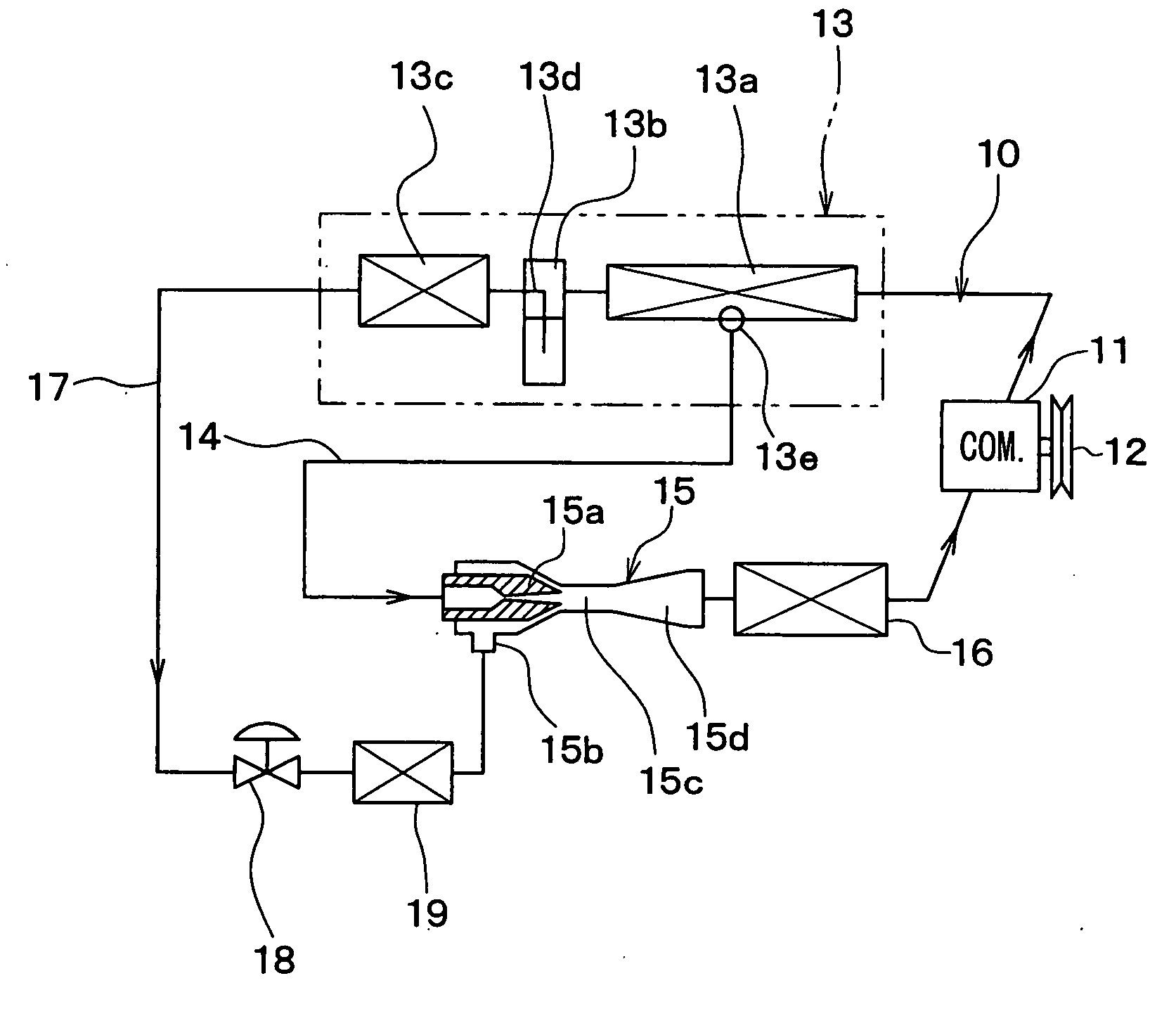
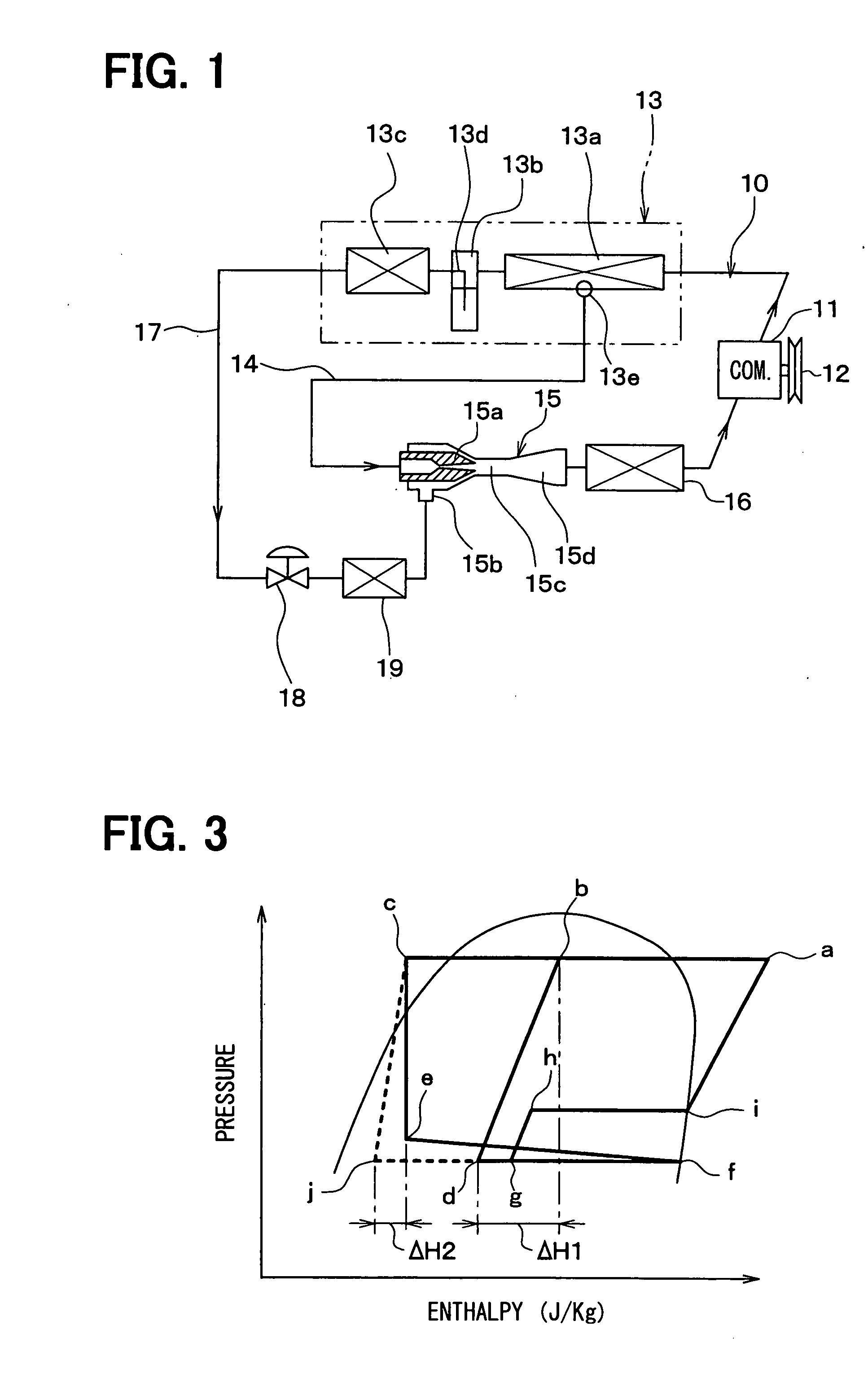
[0025]A first embodiment of the present invention will be now described with reference to FIGS. 1 to 3.

[0026]In this embodiment, a refrigerant cycle device 10 is constructed of a vapor-compression subcritical cycle using refrigerant whose high pressure does not exceed the critical pressure, such as flon-based or HC-based refrigerant, for example.

[0027]In the refrigerant cycle device 10 of this embodiment, a compressor 11 for sucking and compressing the refrigerant is rotatably driven by an engine for vehicle running (not shown) via a pulley 12, a belt, and the like. The compressor 11 for use may be either a variable displacement compressor for being capable of adjusting a refrigerant discharge capacity depending on a change in compression capacity, or a fixed displacement compressor for adjusting a refrigerant discharge capacity by changing an operating efficiency of the compressor by intermittent connection of an electromagnetic clutch. The use of an electric compressor as the comp...

second embodiment

[0067]FIG. 4 shows a refrigerant cycle device 10 according to a second embodiment of the invention.

[0068]In the refrigerant cycle device 10 of the second embodiment, the first evaporator is withdrawn with respect to the refrigerant cycle device 10 of the first embodiment shown in FIG. 1. Thus, the invention may be applied to the refrigerant cycle device 10 in which one evaporator 19 is located only between the downstream side of the refrigerant flow of the throttle mechanism 18 and the refrigerant suction port 15b of the ejector 15.

[0069]In the second embodiment, the other parts of the refrigerant cycle device are similar to those of the above-described first embodiment.

third embodiment

[0070]FIG. 5 shows a refrigerant cycle device 10 according to a third embodiment of the invention.

[0071]In this embodiment, the first evaporator 16 is withdrawn from the cycle structure of the first embodiment shown in FIG. 1, and instead, a low-pressure side vapor-liquid separator 31 is provided on the downstream side of the ejector 15. This vapor-liquid separator 31 separates the low-pressure refrigerant on the downstream side of the ejector 15 into saturated liquid-phase refrigerant and saturated vapor-phase refrigerant to store therein the saturated liquid-phase refrigerant, while allowing the saturated vapor-phase refrigerant to flow toward the suction side of the compressor 11.

[0072]A liquid refrigerant outlet 32 is provided at the bottom of the low-pressure side vapor-liquid separator 31 for taking out the saturated liquid-phase refrigerant. The liquid refrigerant outlet 32 is connected to a refrigerant passage 34 including a check valve 33. The outlet of the refrigerant pass...


PUM


Abstract

In a refrigerant cycle device, a radiator has a heat radiating portion for radiating high-pressure refrigerant discharged from a compressor and a refrigerant outlet downstream from the heat radiating portion, an ejector includes a nozzle portion for decompressing and expanding refrigerant and a refrigerant suction port for sucking refrigerant by high-velocity refrigerant flow jetted from the nozzle portion. The refrigerant cycle device includes a throttle unit for decompressing refrigerant flowing out of the refrigerant outlet of the radiator, an evaporator located between a refrigerant downstream side of the throttle unit and the refrigerant suction port of the ejector, and a branch portion located within the heat radiating portion of the radiator to branch a refrigerant flow. In the refrigerant cycle device, the nozzle portion has a nozzle inlet coupled to the branch portion so that refrigerant flows into the nozzle inlet from the branch portion of the radiator.

Description

CROSS REFERENCE TO RELATED APPLICATION[0001]This application is based on Japanese Patent Application No. 2006-219475 filed on Aug. 11, 2006, the contents of which are incorporated herein by reference in its entirety.FIELD OF THE INVENTION[0002]The present invention relates to a refrigerant cycle device using an ejector as refrigerant decompression and expansion means.BACKGROUND OF THE INVENTION[0003]JP-A-2005-308380 (corresponding to U.S. Pat. No. 7,178,359) discloses a refrigerant cycle device in which a branch portion for branching the flow of refrigerant is provided on the upstream side of a nozzle portion of an ejector and on the downstream side of a radiator. A part of the refrigerant branched flows toward the nozzle portion, while the other refrigerant flows toward a refrigerant suction port of the ejector.[0004]In the refrigerant cycle device as disclosed in JP-A-2005-308380, a first evaporator is disposed on the downstream side of a diffuser of the ejector, and a throttle me...

Claims


Application Information

Patent Timeline
Patent Type & Authority Applications(United States)
IPC IPC(8): F25B1/06
CPCB60H2001/3298F25B9/008F25B40/00F25B2341/0661F25B41/00F25B2309/061F25B2341/0012F25B40/02F25B41/385
Inventor OSHITANI, HIROSHITAKEUCHI, HIROTSUGUTAKANO, YOSHIAKIGOCHO, MIKA
Owner DENSO CORP
Why Eureka
Try Eureka