

Heat exchanging device and heat pump
a technology of heat exchange device and heat pump, which is applied in the direction of heat pump, lighting and heating apparatus, refrigeration components, etc., to achieve the effect of efficiently increasing the pressure of refrigeran
- Summary
- Abstract
- Description
- Claims
- Application Information
AI Technical Summary
Benefits of technology
Problems solved by technology
Method used
Image

Examples
modification 1
[0099](Modification 1)
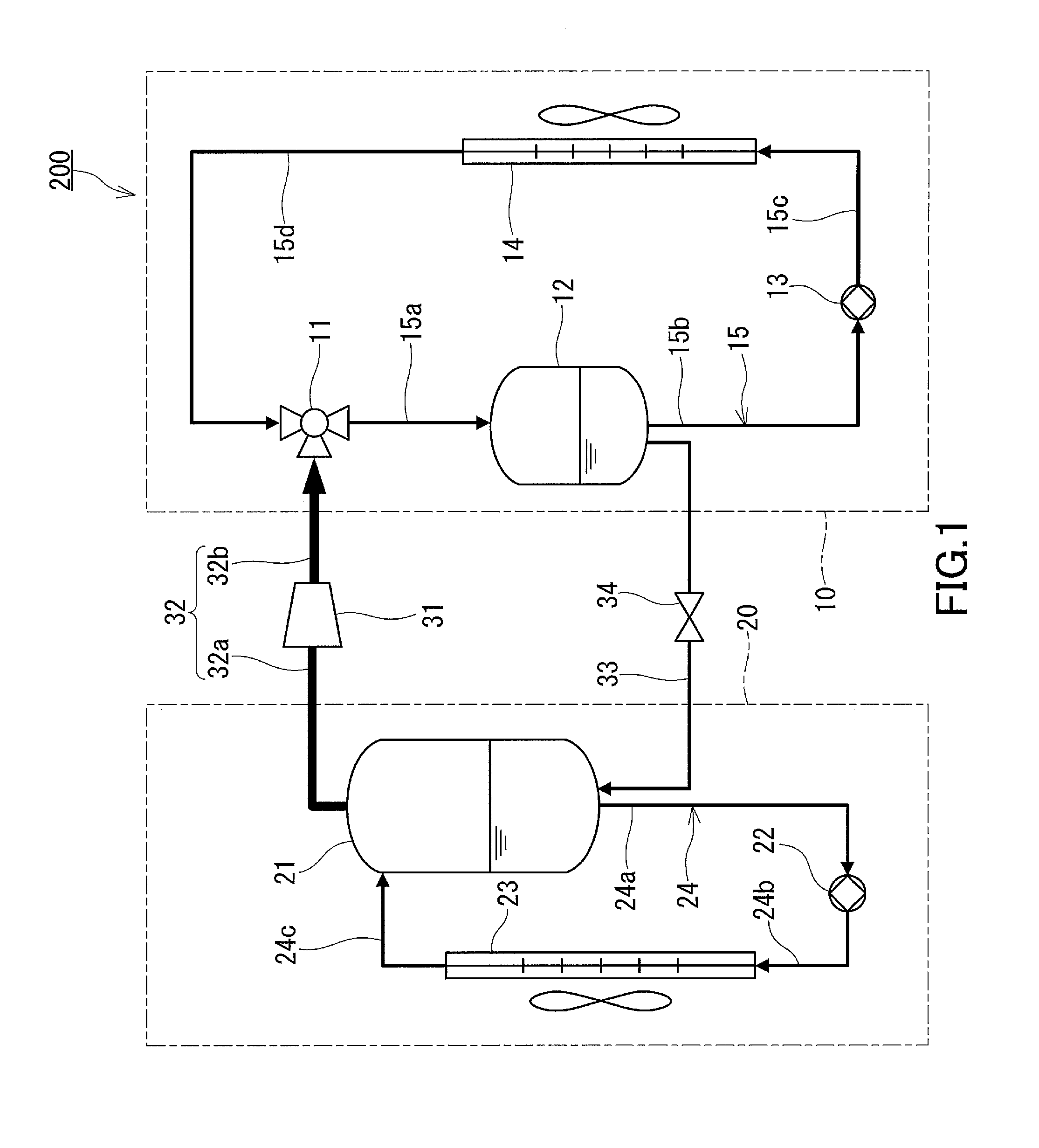
[0100]As shown in FIG. 4, a heat pump apparatus 201 of a modification 1 has a first heat exchange unit 10B having a different configuration from the first heat exchange unit 10 of the heat pump apparatus 200 described with reference to FIG. 1. Specifically, the heat pump apparatus 201 further includes a second pump 16. The other components of the heat pump apparatus 201 are the same as those of the heat pump apparatus 200 described with reference to FIG. 1.
[0101]The second pump 16 is provided between the outlet of the first heat exchanger 14 and the ejector 11 in the liquid path 15. The refrigerant liquid flowing from the first heat exchanger 14 is pumped by the second pump 16 to the ejector 11. In the present modification, the liquid path 15 is formed by pipes 15b to 15e. By the function of the second pump 16, the load on the first pump 13 can be reduced.
[0102]In the heat pump apparatus 201, the pressure at the outlet of the first pump 13 is lower than the pre...
modification 2
[0103](Modification 2)
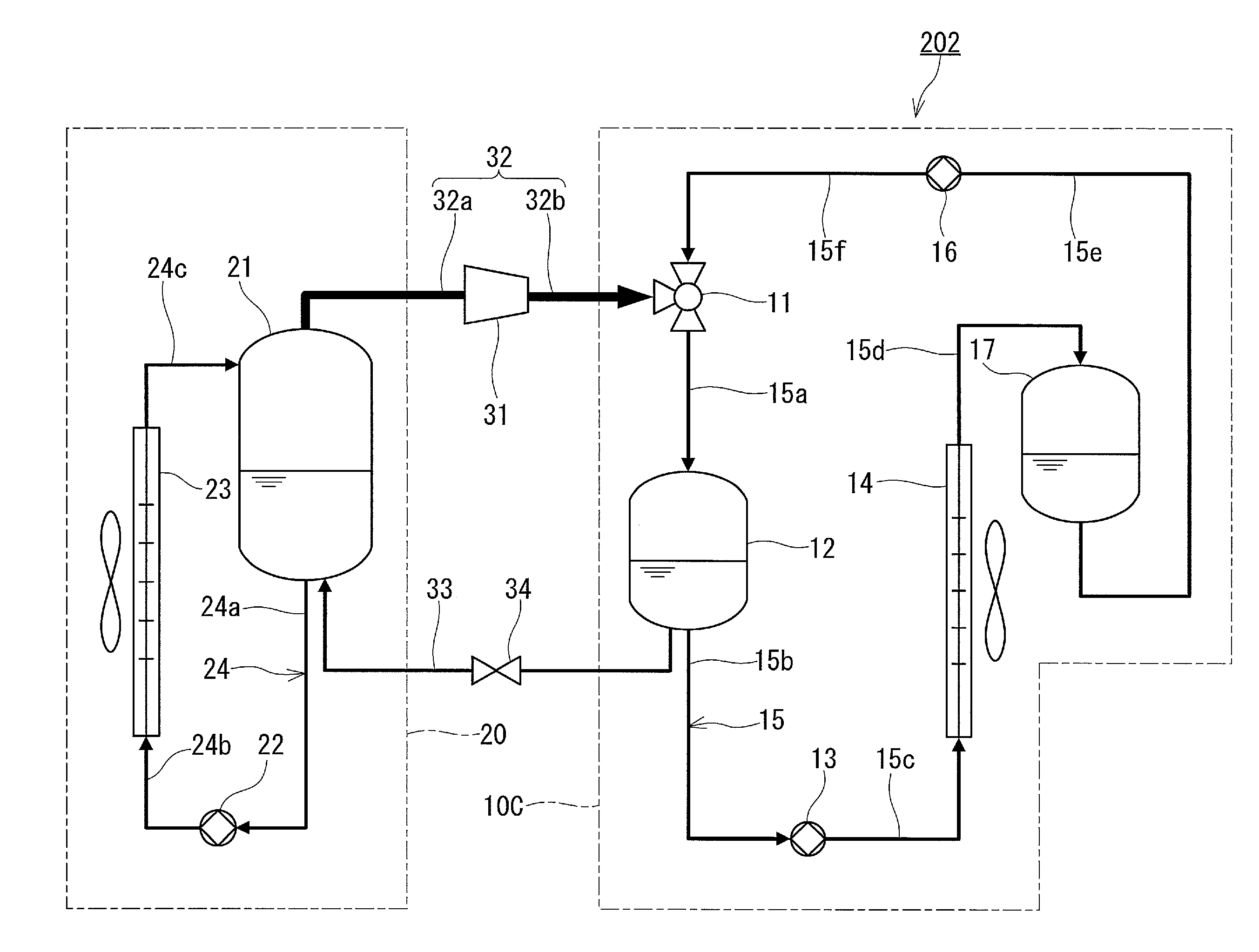
[0104]As shown in FIG. 5, a heat pump apparatus 202 of a modification 2 has a first heat exchange unit 10C having a different configuration from the first heat exchange unit 10 of the heat pump apparatus 200 described with reference to FIG. 1. Specifically, the heat pump apparatus 202 further includes the second pump 16 and a second extractor 17. The other components of the heat pump apparatus 202 are the same as those of the heat pump apparatus 200 described with reference to FIG. 1.
[0105]The second pump 16 is identical to that described in the modification 1, and is provided between the liquid outlet of the second extractor 17 and the ejector 11 in the liquid path 15 so as to pump the refrigerant liquid retained in the second extractor 17 to the ejector 11.
[0106]The second extractor 17 is provided between the outlet of the first heat exchanger 14 and the inlet of the second pump 16 in the liquid path 15. With the second extractor 17, the refrigerant liquid ca...
modification 3
[0108](Modification 3)
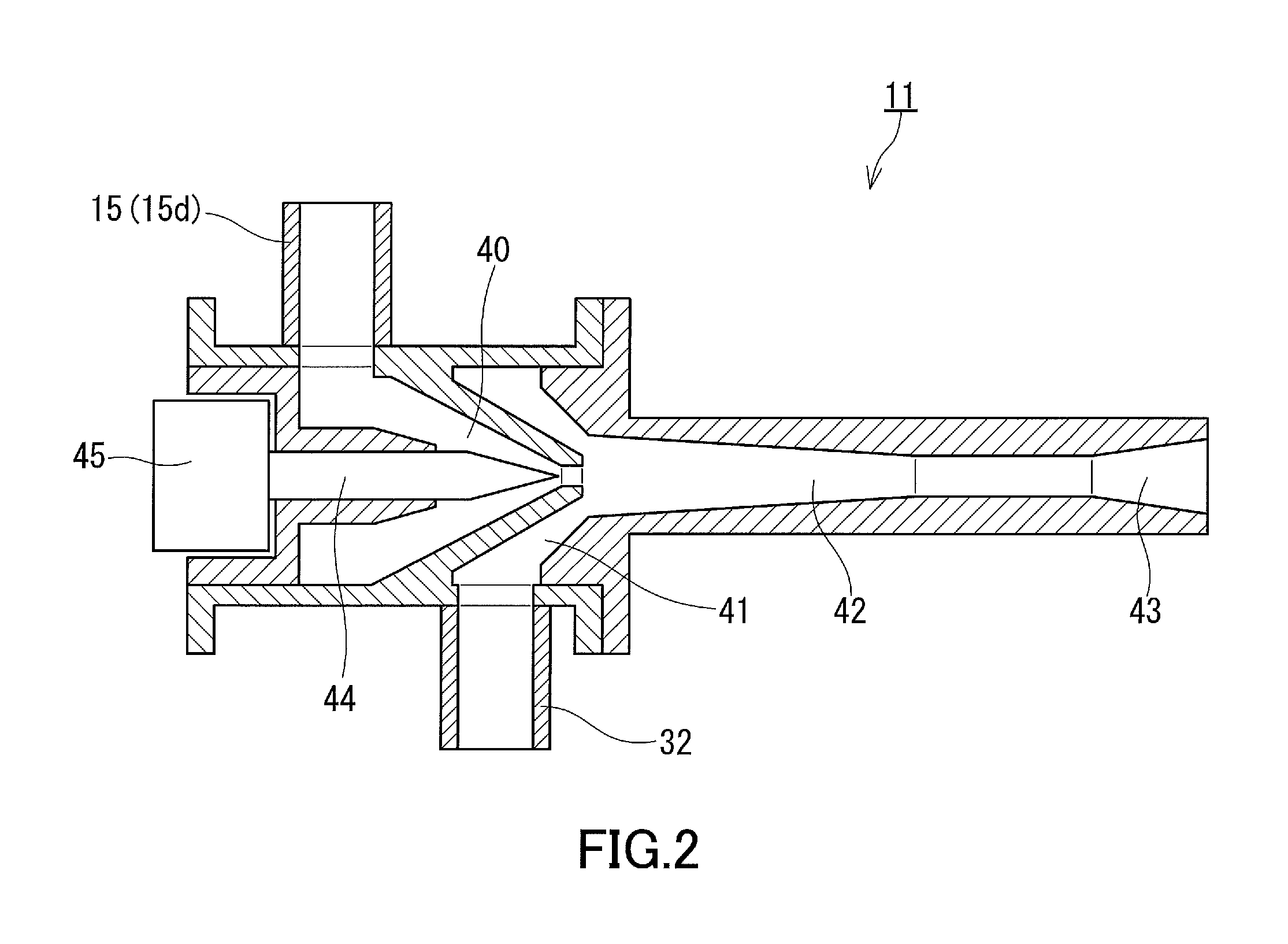
[0109]As shown in FIG. 6, a heat pump apparatus 203 of a modification 3 has a first heat exchange unit 10D having a different configuration from the first heat exchange unit 10 of the heat pump apparatus 200 described with reference to FIG. 1. Specifically, in the heat pump apparatus 203, the first pump 13 is provided between the outlet of the first heat exchanger 14 and the inlet of the ejector 11 in the liquid path 15. The first nozzle 40 of the ejector 11 and the first pump 13 are connected by the pipe 15d. The other components of the heat pump apparatus 203 are the same as those of the heat pump apparatus 200 described with reference to FIG. 1.
[0110]The refrigerant liquid retained in the first extractor 12 is pumped by the first pump 13 to the ejector 11 via the first heat exchanger 14. The discharge pressure of the first pump 13 is lower than atmospheric pressure. The first pump 13 is located at such a positon that both the height from the suction port of ...
PUM
| Property | Measurement | Unit |
|---|---|---|
| temperature | aaaaa | aaaaa |
| pressure | aaaaa | aaaaa |
| pressure | aaaaa | aaaaa |
Abstract
Description
Claims
Application Information