Lubricant return schemes for use in refrigerant cycle

Active Publication Date: 2005-12-29
CARRIER CORP
View PDF22 Cites 7 Cited by
  • Summary
  • Abstract
  • Description
  • Claims
  • Application Information

AI Technical Summary

Benefits of technology

[0005] A control monitors whether this stoppage of the condenser fan is effective to change conditions that are likely indicative of an approaching lubricant shortage. If the conditions continue for a period of time, then a second scheme is implemented. In one embodiment the second scheme includes turning on heater elements that are associated with the evaporator. This increases the load on the evaporator, and ensures that refrigerant mass flow through the evaporator increases.
[0006] Increasing mass flow would tend to entrain more lubricant, and take that lubricant back to the compressor. Further, the increased mass flow traveling through the evaporator ensures that the temperature change in the refrigerant is less at the evaporator. This reduces the likelihood of the refrigerant being boiled out of a lubricant / refrigerant mixture, such that more lubricant is returned to the compressor.
[0007] In a third scheme, if the first two schemes do not operate to correct the problem, a suction modulation valve (SMV) is actuated to open and allow increased mass flow of refrigerant to the compressor. Again, this ensures that lubricant is less likely to remain in the evaporator.

Problems solved by technology

This reduces the likelihood of the refrigerant being boiled out of a lubricant / refrigerant mixture, such that more lubricant is returned to the compressor.

Method used


Image

  • Lubricant return schemes for use in refrigerant cycle
  • Lubricant return schemes for use in refrigerant cycle
  • Lubricant return schemes for use in refrigerant cycle

Examples


Embodiment Construction

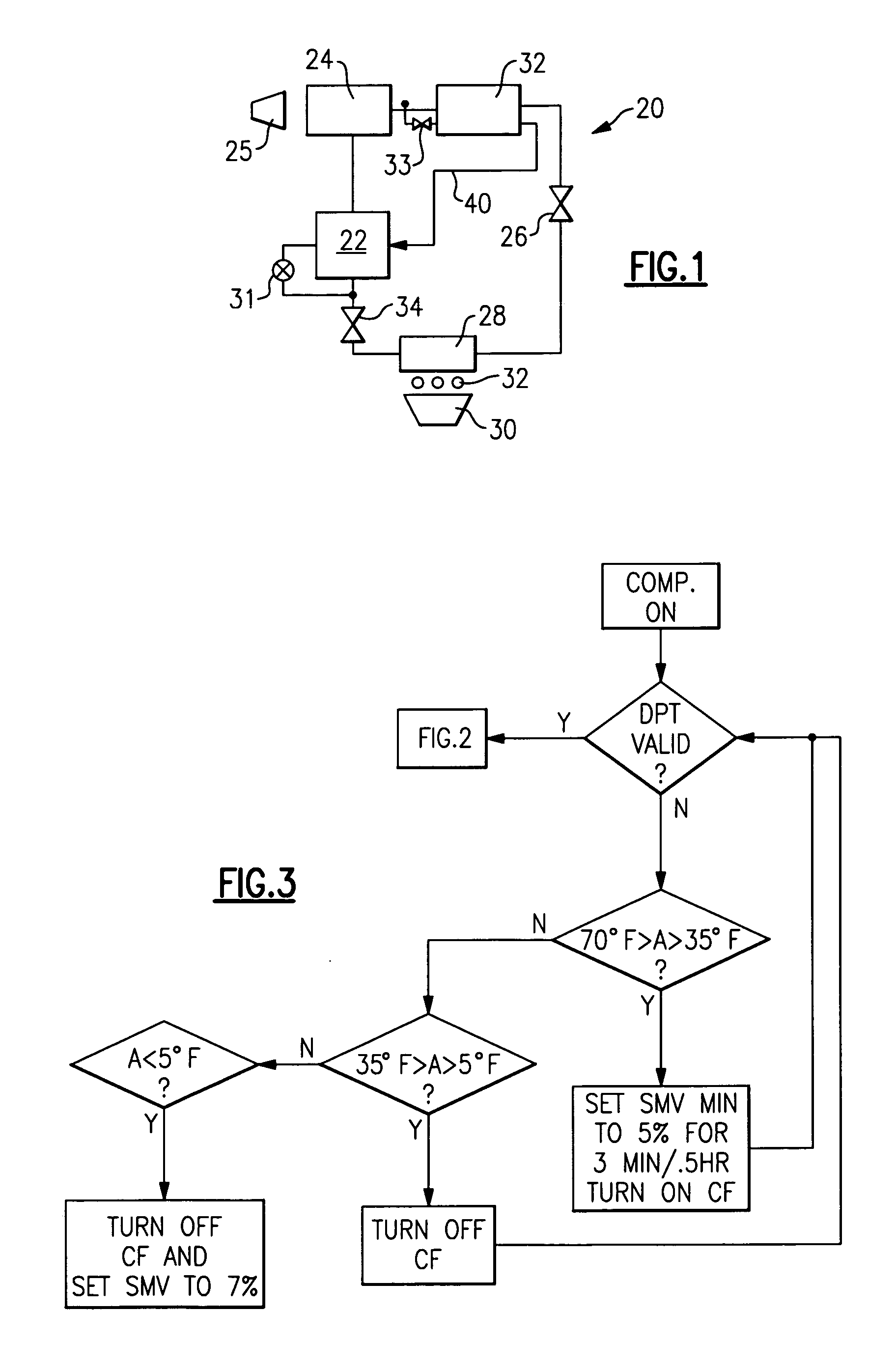
[0014] A refrigerant cycle 20 is illustrated in FIG. 1 having a compressor 22 compressing a refrigerant and delivering the refrigerant to a downstream condenser 24. A fan 25 blows air over the condenser 24. Typically, the condenser is an outdoor heat exchanger.

[0015] From the condenser 24 refrigerant travels to an expansion device 26, and from the expansion device 26 to an evaporator 28. The evaporator is an indoor heat exchanger. As shown, a fan 30 blows air over the evaporator, and that air is typically delivered into an environment to be conditioned. As also shown schematically, heater elements 32 are associated with the evaporator. These heater elements have been placed into some prior art evaporators to melt ice that may accumulate on the evaporator.

[0016] A suction modulation valve 34 is positioned downstream of the evaporator, and upstream of the compressor 22. The suction modulation valve is able to modulate the suction pressure of the refrigerant reaching the compressor 2...


PUM


Abstract

A control algorithm is developed which takes corrective action in the event that system conditions indicate there may be an inadequate flow of lubricant in the system. In particular, if a discharge pressure is below a predetermined amount or if the suction modulation valve is throttled, there is a possibility of inadequate lubricant flow. The system control then turns off the condenser fan, and if that first step is not sufficient, may also turn on an evaporator heater and then control a suction modulation valve. A fail safe control loop also takes effect if the condition sensor appears to have failed.

Description

BACKGROUND OF THE INVENTION [0001] This invention relates to schemes for improving lubricant flow, and in particular, the return of lubricant from various locations in a refrigerant cycle back to a compressor, to prevent an inadequate supply of lubricant to the compressor. [0002] Refrigerant cycles typically include a compressor for compressing a refrigerant and delivering that refrigerant downstream to a condenser. From the condenser the refrigerant passes to an expansion device that expands the refrigerant. From the expansion device, refrigerant moves to an evaporator. The evaporator is a heat exchanger that typically changes the temperature in an environment to be conditioned. From the evaporator, the refrigerant may run through a modulation valve before returning to the compressor. The evaporator often captures refrigerant and lubricant as it has traveled through the refrigerant cycle. Lubricant is typically necessary in the compressor to lubricate the moving parts. However, as ...

Claims


Application Information

Patent Timeline
IPC IPC(8): F25B31/00F25B41/04F25B43/02F25B49/00
CPCF25B31/004F25B41/043F25B49/005F25B2400/01F25B2400/13Y02B30/743F25B2500/16F25B2600/111F25B2700/1931F25B2700/2106F25B2500/06F25B41/22Y02B30/70
Inventor SCARCELLA, JASON D.LIFSON, ALEXANDER
Owner CARRIER CORP
Why Eureka
Try Eureka