Refrigeration Unit

a refrigeration unit and refrigeration technology, applied in the field of refrigeration equipment, can solve the problems of reducing the refrigeration capability of the refrigeration equipment, reducing the heat exchange capacity of the heat exchanger, and forming frost on the outdoor heat exchanger, so as to reduce the amount of frost

Inactive Publication Date: 2008-02-14
DAIKIN IND LTD
View PDF9 Cites 21 Cited by
  • Summary
  • Abstract
  • Description
  • Claims
  • Application Information

AI Technical Summary

Benefits of technology

[0010] The present invention provides a refrigeration apparatus that reduces the amount of frost that forms when a heat exchanger is operated as an evaporator. Means of Solving the Problems

Problems solved by technology

The frost formation lowers the heat exchanging capability of the heat exchanger, and consequently lowers the refrigeration capability of the refrigeration apparatus.
As a result, frost forms on the outdoor heat exchanger.
The frost formation lowers the evaporation capability of the outdoor heat exchanger, and consequently lowers the heating capability of the air conditioner.
However, the defrosting operation may suspend the heating operation of the air conditioner or lower the heating capability of the air conditioner depending on the type of defrosting operation.
This may lower the heating comfort of the air conditioner.
Thus, even if the water slippage and the water repellency of the surface of the plate fins 43 is increased, a refrigeration apparatus using the conventional heat exchanger 42 would not sufficiently benefit from the resulting formation reduction effect.

Method used


Image

  • Refrigeration Unit
  • Refrigeration Unit
  • Refrigeration Unit

Examples


first embodiment

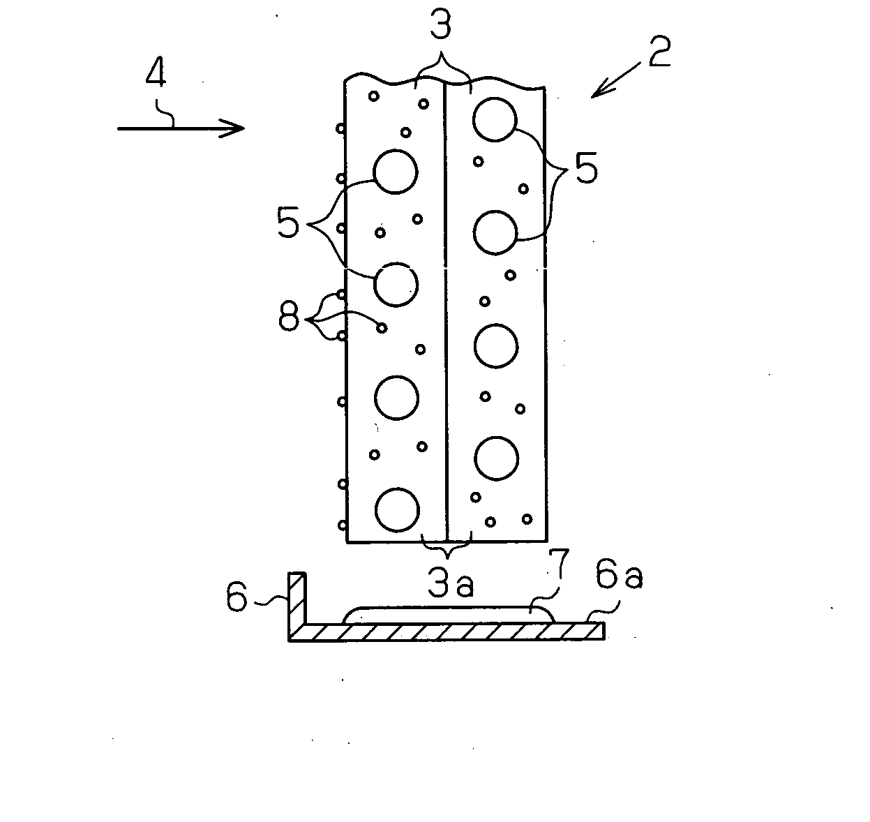
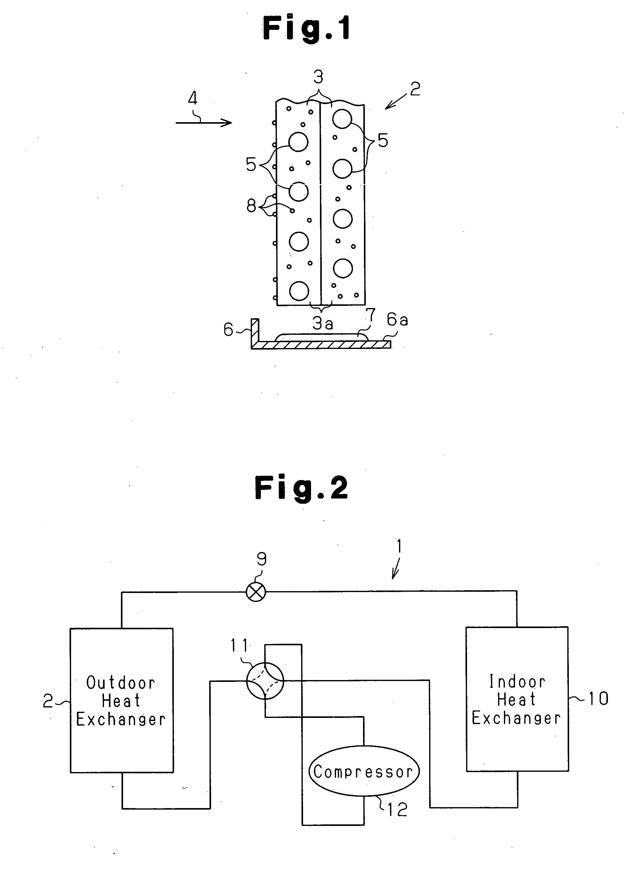
[0033]FIG. 1 is a cross-sectional view showing a portion of an outdoor heat exchanger 2 used in an air conditioner 1 according to a first embodiment of the present invention. FIG. 2 is a circuit diagram showing a refrigerant circuit of the air conditioner 1.

[0034] In the air conditioner 1, the outdoor heat exchanger 2, an expansion valve 9, an indoor heat exchanger 10, a four-way switch valve 11, and a compressor 12 are connected by a refrigerant pipe to form a refrigerant circuit as shown in FIG. 2. During a cooling operation of the air conditioner 1, the four-way switch valve 11 is set as indicated by solid lines in FIG. 2. In this state, a refrigerant serving as a heating medium discharged from the compressor 12 circulates in the order of the four-way switch valve 11, the outdoor heat exchanger 2, the expansion valve 9, the indoor heat exchanger 10, and the four-way switch valve 11, and is sucked into the compressor 12. As a result of circulation of the refrigerant, the outdoor ...

second embodiment

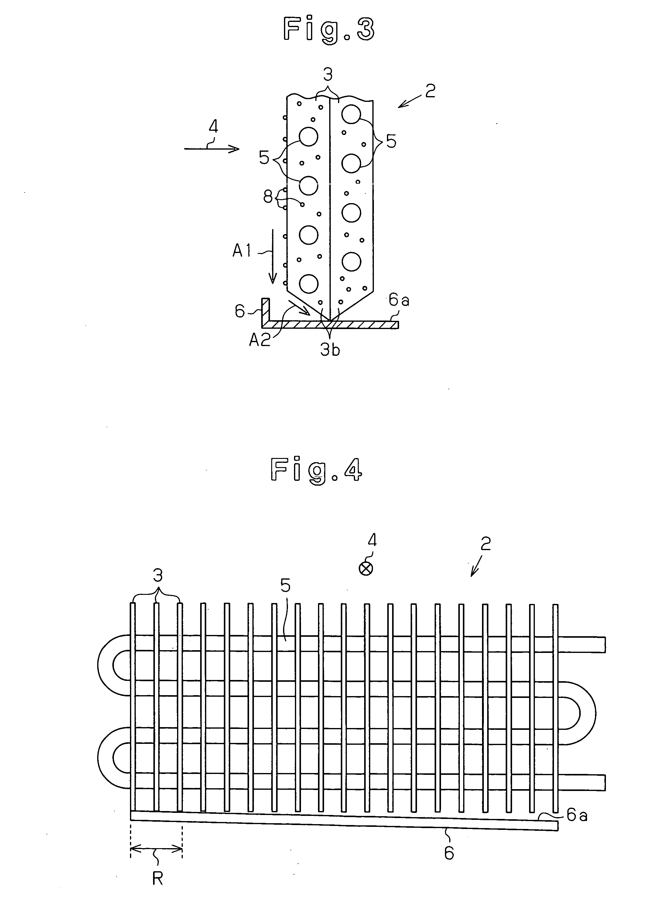
[0044] A second embodiment of the present invention will now be described with reference to FIGS. 3 to 5. The structure of the second embodiment is the same as the structure of the first embodiment except in the shape of the outdoor heat exchanger 2 and the positional relationship between the outdoor heat exchanger 2 and the drain pan 6. The components of the second embodiment common to the first embodiment will not be described in detail.

[0045]FIG. 3 is a cross-sectional view showing a portion of an outdoor heat exchanger 2 according to the second embodiment of the present invention. FIG. 4 is a rear view showing the outdoor heat exchanger 2 as viewed from a downstream side in an air circulation direction 4.

[0046] As shown in FIG. 4, the outdoor heat exchanger 2 of the second embodiment is arranged in a manner such that its lower end partially comes into contact with an upper surface 6a of a drain pan 6. Thus, the lower end of the outdoor heat exchanger 2 is supported by the drai...

third embodiment

[0056] A third embodiment of the present invention will now be described with reference to FIG. 6. The structure of the third embodiment is the same as the structure of the second embodiment except in the shape of the outdoor heat exchanger 2. The components of the third embodiment common to the second embodiment will not be described in detail.

[0057]FIG. 6 is a rear view showing a portion of an outdoor heat exchanger 2 according to the third embodiment of the present invention as viewed from a downstream side in an air circulation direction 4.

[0058] In the third embodiment, projections are formed on lower ends of some plate fins 3L in such a manner that the projections extend more downward than lower ends of other plate fins 3S. More specifically, two types of plate fins 3L and 3S that differ in vertical length are used (reference numeral 3 refers generically to the two different plate fins), and each of the plate fins 3L with the long vertical length is arranged at every predete...


PUM

PropertyMeasurementUnit
temperatureaaaaaaaaaa

Abstract

An air conditioner comprises an outdoor heat exchanger having a plate fin whose surface is treated to have water-sliding properties and water repellency and a drain pan arranged under the outdoor heat exchanger. There is a gap throughout between the lower end portion of the outdoor heat exchanger and the upper surface of the drain pan. Water droplets condensed when the outdoor heat exchanger operates as an evaporator fall on the drain pan from the lower end portion of the plate fin. Since the plate fin and the drain pan are not in contact with each other, there is no such case that ice adheres to the contact portion and frost develops therefrom.

Description

TECHNICAL FIELD [0001] The present invention relates to a refrigeration apparatus formed by a heat exchanger that has a heat exchanging surface. BACKGROUND ART [0002] In a refrigeration apparatus in which a heat exchanger is operated as an evaporator, frost usually forms on a heat exchanging surface of the heat exchanger when the temperature of air with which the heat exchanger exchanges heat is low or when the evaporation temperature of the evaporator is low. The frost formation lowers the heat exchanging capability of the heat exchanger, and consequently lowers the refrigeration capability of the refrigeration apparatus. [0003] For example, in the case of a heat pump type air conditioner, which is one type of refrigeration apparatus, the evaporation temperature of an outdoor heat exchanger operating as an evaporator decreases when the outdoor air temperature decreases during operation. As a result, frost forms on the outdoor heat exchanger. The frost formation lowers the evaporati...

Claims


Application Information

Patent Timeline
Patent Type & Authority Applications(United States)
IPC IPC(8): F28F13/18F25D21/14
CPCF24F1/18F24F1/36F24F13/22F28F17/005F25B40/02F28F1/32F28F13/04F25B13/00F25B39/02F28F13/18F28F17/00
Inventor KAMADA, TOSHIMITSUYOSHIOKA, SHUNNAKATA, HARUOKOBAYASHI, SHINICHIROUKIDO, TERUO
Owner DAIKIN IND LTD
Why Eureka
Try Eureka