Twin Fin Fairing

Active Publication Date: 2008-02-14
SEAHORSE EQUIP
View PDF20 Cites 21 Cited by
  • Summary
  • Abstract
  • Description
  • Claims
  • Application Information

AI Technical Summary

Benefits of technology

[0013]The subject invention is directed to a fairing for the reduction of vortex-induced vibration, the minimization of drag and the elimination of galloping about a substantially cylindrical element immersed in a fluid medium. The fairing has a U-shaped cylindrical shell with opposing edges defining a longitudinal gap and parallel fins extending outwardly from the opposing edges of the shell, the parallel fins b

Problems solved by technology

While those waters may bring the reserves they seek, the offshore producers are also faced with stronger currents threatening the structural integrity of their risers, pipelines, and other elongated and cylindrical components involved in oil and gas production.
If the frequency of this harmonic load is near the resonant frequency of the riser, large vibrations transverse to the current can occur.
This results in more energy transfer from the current to the riser, and hence more drag.
The movement of oil and gas exploration, development and production into deep and ultra-deep waters has created unique engineering challenges requiring innovative engineering solutions.
One particular challenge is the vortex-induced-vibrations (VIV) of long drilling and production risers.
The resulting vibration increases drag, reduces fatigue life and left unchecked may lead to the failure of the marine element or its supports.
Strakes and shrouds can be effective regardless of the current orientation, but they tend to increase the drag acting on the riser.
While fairings can be effective for reducing VIV, a number of problems still exis

Method used


Image

  • Twin Fin Fairing
  • Twin Fin Fairing
  • Twin Fin Fairing

Examples


Embodiment Construction

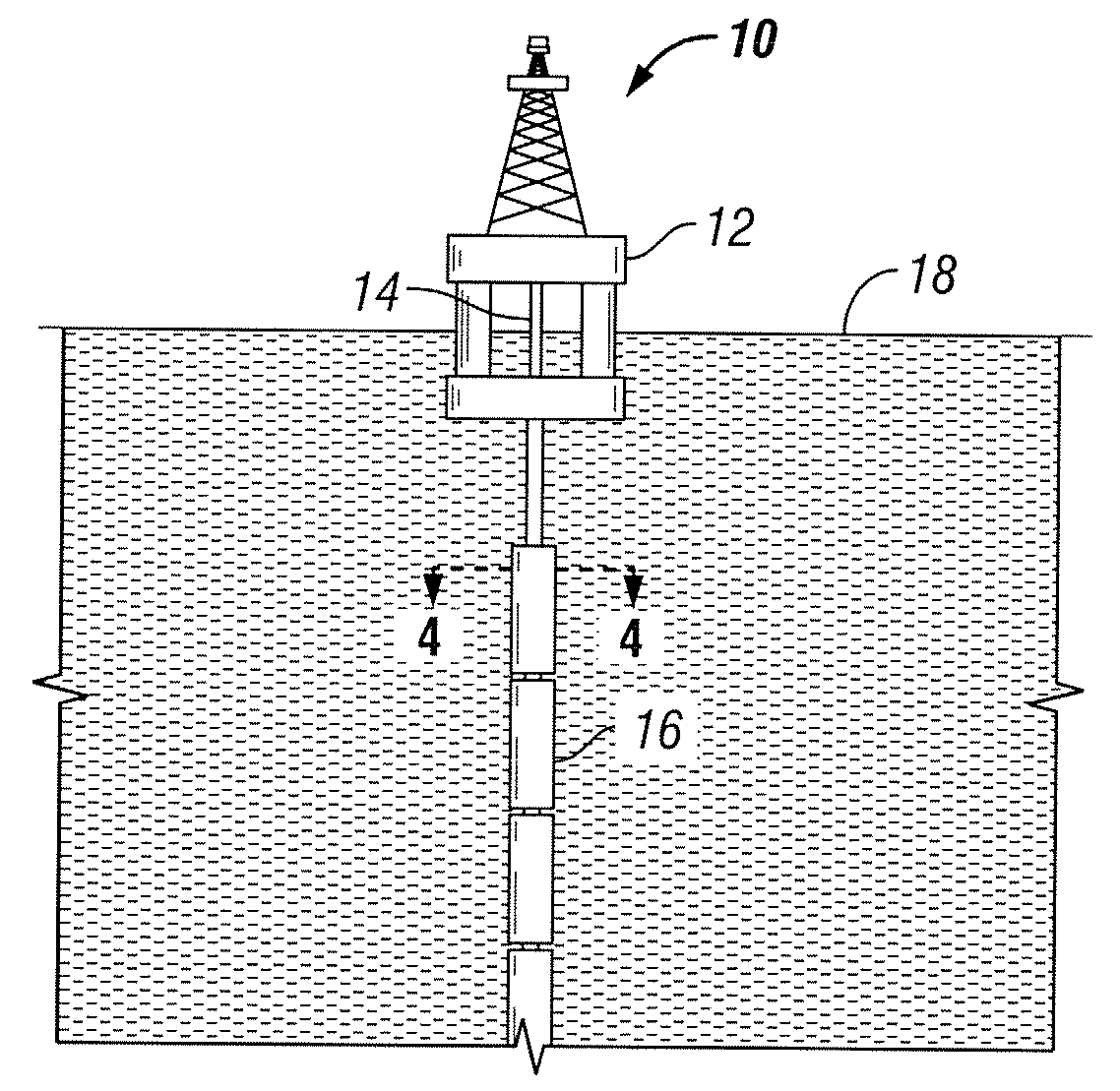
[0053]The present invention is directed to rotating fairings that include specifically placed fins for the reduction of vortex-induced vibration (“VIV”) on pipes or other structural components immersed in fluid. As discussed above, when a solid object is exposed to fluid flows vibration results from vortices shed off the object when the fluid flows by it. The flow pattern around a cylinder can be characterized by the Reynolds Number (Re) of the incident flow and the location where flow separates from the cylinder surface which depends on whether the boundary layer is turbulent or laminar. In the subcritical range, the Reynolds number range is 300


PUM


Abstract

A fairing for the reduction of vortex-induced vibration and the minimization of drag about a substantially cylindrical element immersed in a fluid medium. The fairing also eliminates the galloping phenomenon typically associated with a teardrop-shaped fairing. The fairing having a U-shaped cylindrical shell with opposing edges defining a longitudinal gap and parallel fins extending outwardly from the opposing edges of the shell, the parallel fins being positioned so as to reduce vortex-induced vibration, minimize drag and to eliminate the galloping phenomenon on the cylindrical element.

Description

CROSS REFERENCE TO RELATED APPLICATIONS[0001]This application is a continuation-in-part of U.S. Ser. No. 11 / 463,413 filed Aug. 9, 2006 which is herein incorporated in its entirety.TECHNICAL FIELD[0002]The present invention relates generally to the reduction of vortex-induced vibration (“VIV”) and more particularly to a fairing used for the reduction of VIV on pipes or other structural components immersed in a fluid.BACKGROUND OF THE INVENTION[0003]Exploration for oil and natural gas reserves led drillers offshore many years ago and as offshore exploration continues, offshore producers find themselves in deeper and deeper waters. While those waters may bring the reserves they seek, the offshore producers are also faced with stronger currents threatening the structural integrity of their risers, pipelines, and other elongated and cylindrical components involved in oil and gas production.[0004]Stresses on the pipes or other structural components immersed in fluid, such as drilling rise...

Claims


Application Information

Patent Timeline
IPC IPC(8): E21B17/00
CPCF15D1/10E21B17/01F16L1/12F16L1/123
Inventor MASTERS, RODNEY H.MASTERS, RANDY W.SYKES, MICHAEL
Owner SEAHORSE EQUIP
Why Eureka
Try Eureka