Lamp or LED failure monitoring system

a failure monitoring and led technology, applied in the direction of lamps testing, light sources, instruments, etc., can solve the problems of lamp failure, panel to sound the alarm, and considerable primary curren

Active Publication Date: 2008-02-14
JILIAN A MCDERMOTT CORP
View PDF5 Cites 8 Cited by
  • Summary
  • Abstract
  • Description
  • Claims
  • Application Information

AI Technical Summary

Problems solved by technology

Also, a break in the wiring can drop the current to zero and cause the panel to sound the alarm.
Also, the LEDs drain much less than incandescent lamps so the alarm panels would indicate lamp failure even though the LEDs were still giving off light.
However, transformers have idle currents, or eddy currents, and therefore there would be a current in the primary winding when no load is connected to the secondary winding of the transformer.
Under these conditions, alarm panels will not detect a burned out LED or low voltage incandescent bulb because there is always some primary current.
Unfortunately, this primary current is considerable and unless the alarm panels are adjusted precisely, an alarm will not sound.
This makes operation of the alarm panels presently in use virtually impossible or impractical with these new types of LEDs or low power incandescent lights.
These and other panel designs do not function properly when attached to LEDs, or low voltage incandescent lamp circuits.
Similarly, LEDs and low voltage incandescent lamps cannot be installed in conjunction with presently available alarm panels.

Method used


Image

  • Lamp or LED failure monitoring system
  • Lamp or LED failure monitoring system
  • Lamp or LED failure monitoring system

Examples


Embodiment Construction

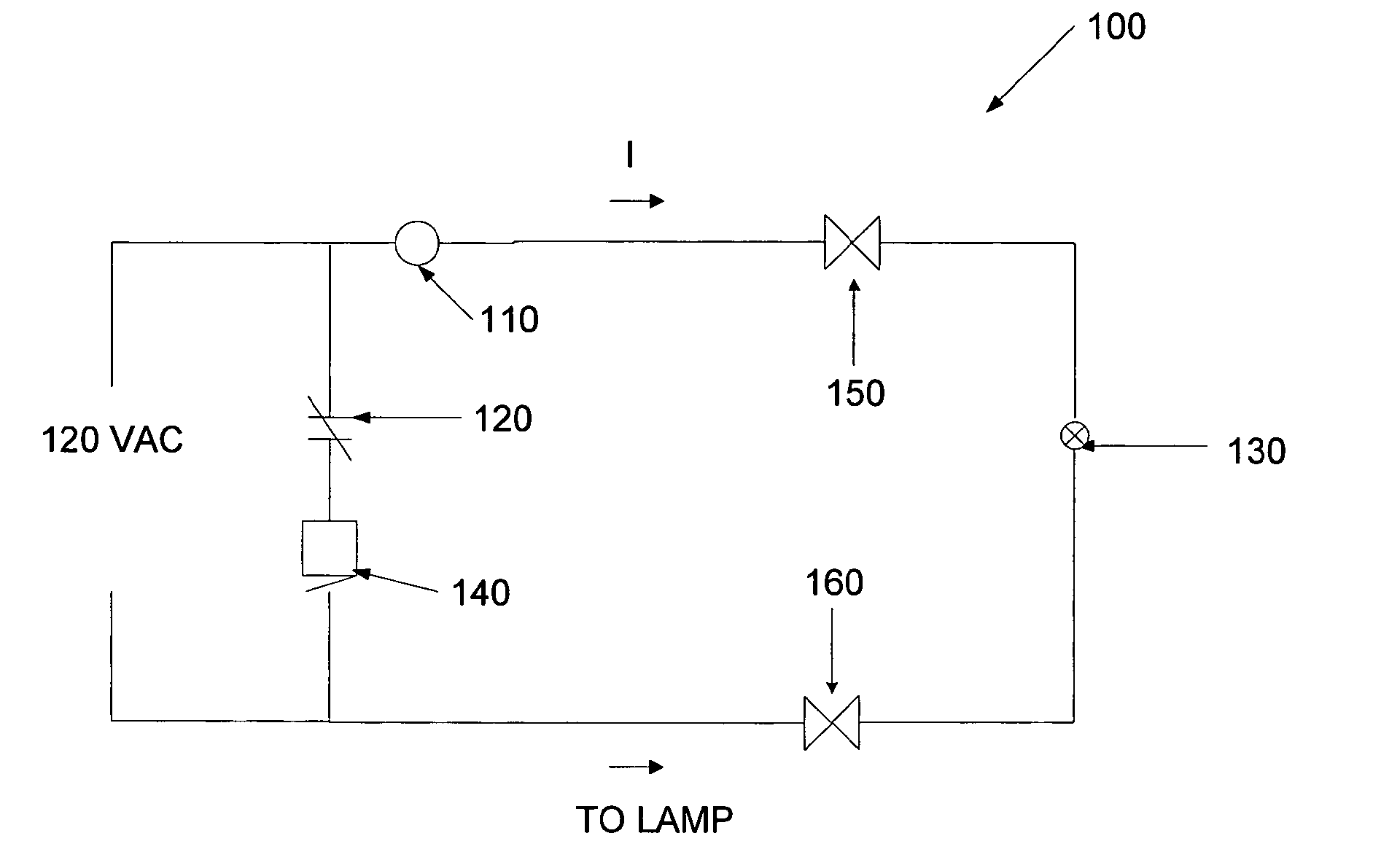
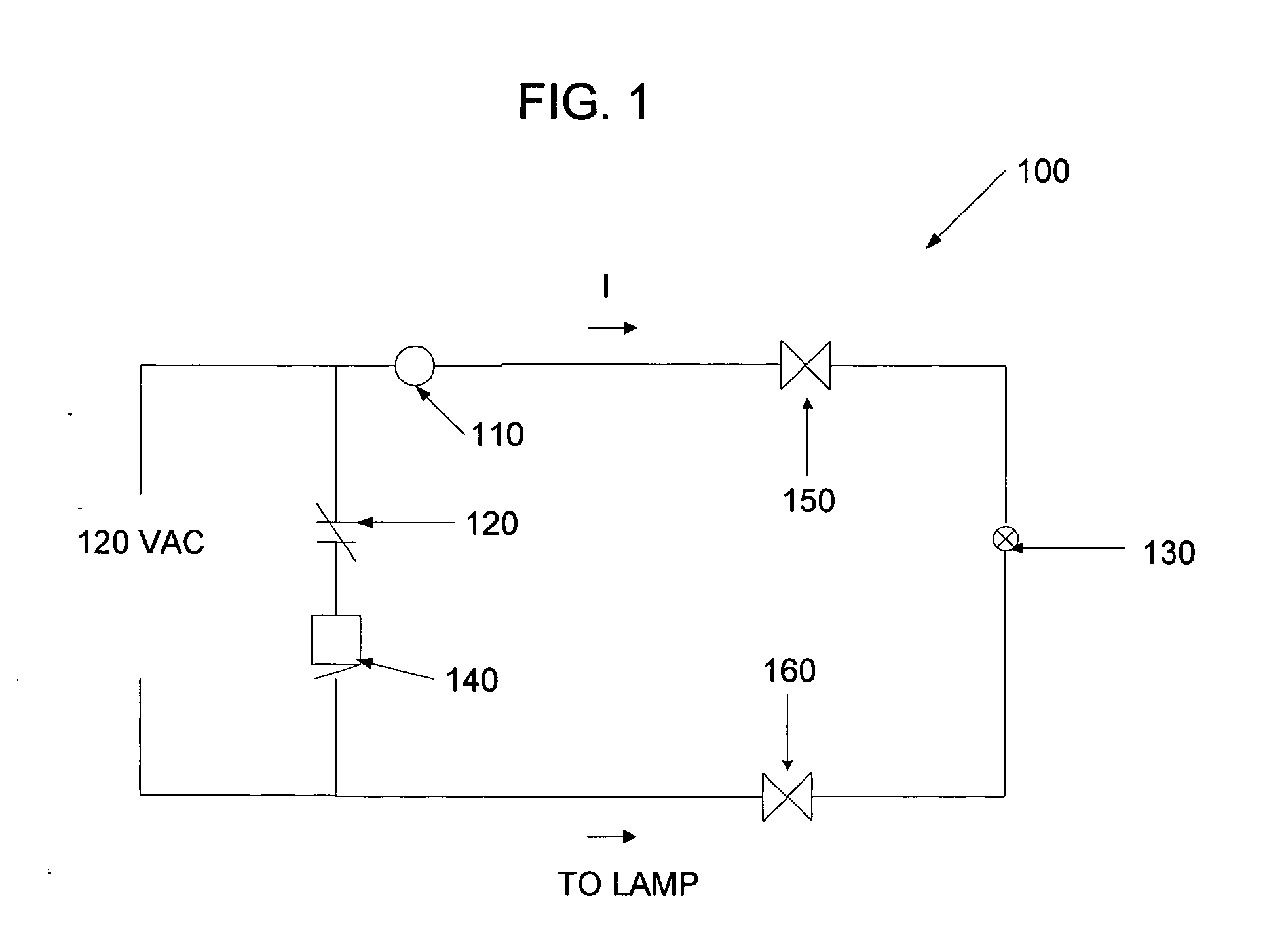
[0018] The present invention relates to a mechanism for monitoring LEDs or low voltage incandescent lamps using existing alarm panels. With reference to FIG. 3, an exemplary embodiment of an electrical circuit 300 in accordance with the present invention is illustrated. As shown in FIG. 3, electrical circuit 300 comprises, for purposes of illustration, two circuits identified in FIG. 3 as circuit 1 and circuit 2. In FIG. 3, electrical circuit 300 is connected to an alarm panel, such as that shown in FIGS. 1 or 2, in lieu of lamp 130 or lamp 210, respectively, and a voltage is thereby applied from the alarm panel. As will be described in detail below, circuit 1 begins at the connections to one of the above-described alarm panels and ends at the primary winding P1 of transformer 380 and circuit 2 begins at the secondary winding P2 of transformer 380 and includes a light sensing device. In FIG. 3, the dashed lines indicate that lamp 310 rather than LEDs 320 may be connected to electric...


PUM


Abstract

A light failure monitoring system using existing alarm panels includes a first circuit capable of turning on a solid state switch or transistor, which turns on a lamp or LEDs. The system also includes a second circuit having a light sensitive device, such as a photoresistor, that keeps the solid state switch or transistor turned on upon sensing light from the lamp or LEDs, and when the light sensed by the photoresistor substantially drops in intensity the solid state switch or transistor turns off, which causes an alarm to sound on the alarm panel. Alternatively, the first circuit may include a second solid state switch to amplify the signal and make it easier to start the second circuit.

Description

This application claims the benefit of U.S. Provisional Application No. 60 / 832,652, filed Jul. 21, 2006, the entire disclosure of which is hereby incorporated by reference.FIELD OF THE INVENTION [0001] The present invention relates to a system of enabling light-emitting diodes (“LEDs”) or low voltage incandescent lamps to be monitored by alarm panels. More specifically, the present invention relates to a system for detecting partial or full loss of light emitted from an LED light source or low voltage incandescent lamp fixtures when attached to alarm panels which detect drops in current caused by lamp failures. BACKGROUND OF THE INVENTION [0002] Generally, marine running lights on larger vessels and workboats such as Tug boats mostly operate off 120 VAC. Many of these boats have alarm panels that sound an alarm if one of the running lights burns out. As long as the current drain appreciably drops close to zero, then the alarm panel can detect that a light is burned out. In these sys...

Claims


Application Information

Patent Timeline
Patent Type & Authority Applications(United States)
IPC IPC(8): G08B21/00
CPCB60Q11/005H05B37/03G01R31/44H05B47/20
Inventor MCDERMOTT, VERNON C. SR.
Owner JILIAN A MCDERMOTT CORP
Why Eureka
Try Eureka