Focusing information visualization device, and corresponding method, program and recording medium

a technology of focusing information and visualizing information, which is applied in the field of visualizing focusing information of photographic images, can solve the problems of not being able to accurately detect the position of focus, and achieve the effect of ensuring the focusing status of photographic images on the screen

Active Publication Date: 2008-02-14
138 EAST LCD ADVANCEMENTS LTD
View PDF4 Cites 24 Cited by
  • Summary
  • Abstract
  • Description
  • Claims
  • Application Information

AI Technical Summary

Benefits of technology

[0011]The focusing information visualization device of the invention refers to the preset focusing condition and extracts an edge judged as focused from a photographic image. The focusing information based on the extracted edge is output in a visually recognizable manner on the screen. This arrangement enables the user to readily check the focusing status of the photographic image on the screen. The output focusing information is effectively used for the focus judgment of the photographic image.

Problems solved by technology

These prior art image processing devices give certain levels of information for focus judgment but are not capable of accurately detecting the position of focus.

Method used


Image

  • Focusing information visualization device, and corresponding method, program and recording medium
  • Focusing information visualization device, and corresponding method, program and recording medium
  • Focusing information visualization device, and corresponding method, program and recording medium

Examples


first embodiment

(1) First Embodiment

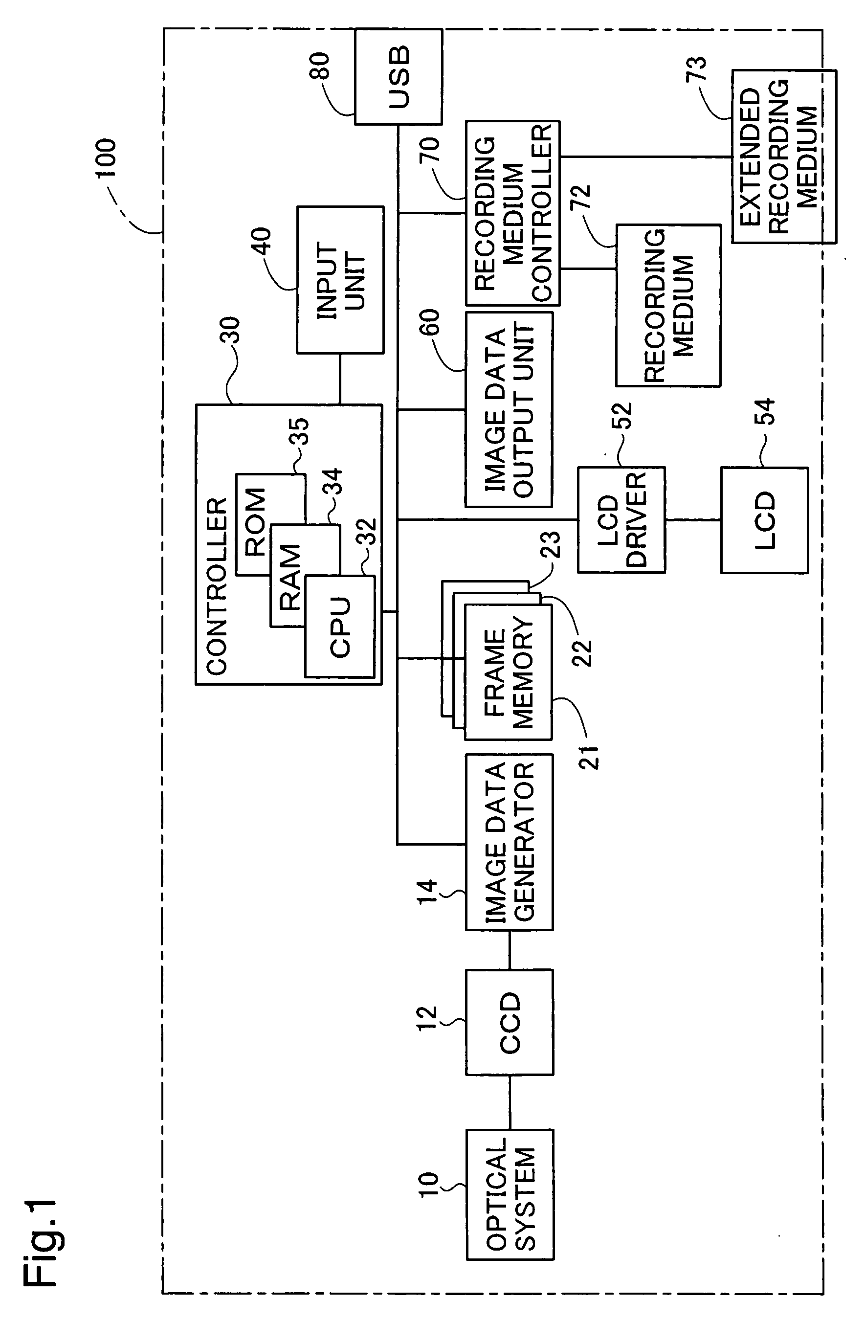
[0025]FIG. 1 schematically illustrates the basic structure of a digital still camera 100 in a first embodiment of the invention. As shown in FIG. 1, the digital still camera 100 includes an optical system 10, a CCD 12, an image data generator 14, a frame memories 21, 22, and 23, a controller 30, an input unit 40, an LCD driver 52, an LCD 54, an image data output unit 60, a recording medium controller 70, a recording medium 72, an extended recording medium 73, and a USB interface 80.

[0026]The optical system 10 has a lens and a diaphragm mechanism to form an optical image as an imaging object on the CCD 12. The CCD 12 converts the optical image formed by the optical system 10 into an electrical signal. The image data generator 14 processes the electrical signal input from the CCD 12 and outputs the processed signal as multivalued (R, G, B) raster data (image data) to the frame memory 21.

[0027]The frame memory 21 is generally used as a memory for display of images o...

second embodiment

(2) Second Embodiment

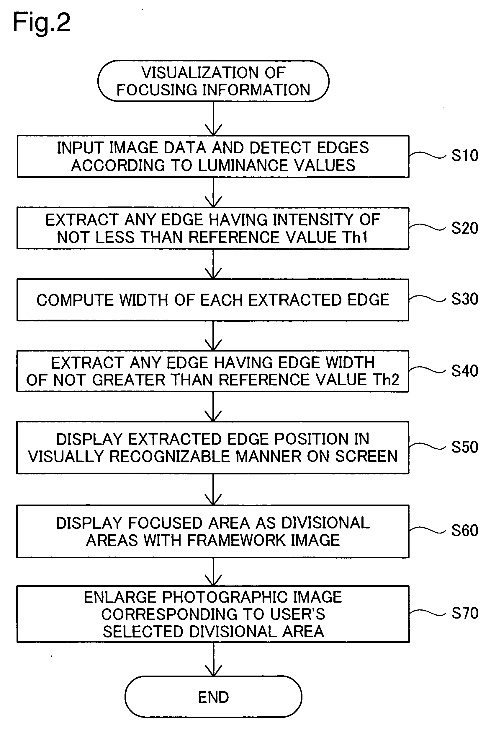
[0047]A digital still camera in a second embodiment of the invention described below has the same hardware configuration as that of the digital still camera 100 in the first embodiment of the invention. The difference from the first embodiment is only part of the focusing information visualization process for extraction of edges. The focusing information visualization process of the second embodiment executes the processing of steps S110 to S145 shown in the flowchart of FIG. 7, in place of the processing of steps S10 to S40 of the first embodiment shown in the flowchart of FIG. 2. In the focusing information visualization process of the second embodiment, the controller 30 first computes a luminance difference ΔZ between an n-th pixel and an adjacent pixel aligned in a predetermined direction (step S110). In the second embodiment, the luminance difference is computed in both the horizontal direction and the vertical direction. FIG. 8 shows computation of the lu...

third embodiment

(3) Third Embodiment

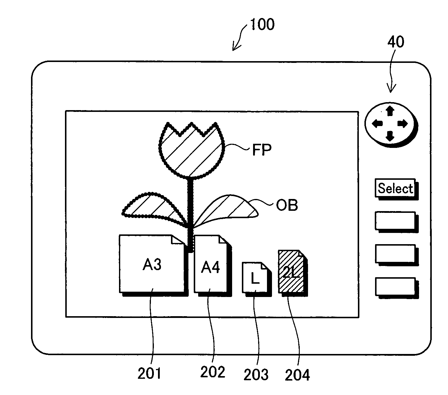
[0053]A digital still camera in a third embodiment of the invention described below has the same hardware configuration as those in the first and the second embodiments of the invention. The difference from the first embodiment is only part of the focusing information visualization process for display of the extracted edge. The focusing information visualization process of the first embodiment displays the position of an extracted edge as a focused area in a visually recognizable manner on the LCD 54 at step S50 in the flowchart of FIG. 2. In the first embodiment, the edge position display FP is laid over the object image OB at the position of the edge extraction as shown in FIG. 6A. The focusing information visualization process of the third embodiment, on the other hand, extracts an edge as a focused area from the whole image and displays a processed image corresponding to the position of the edge extraction at step S150 in the flowchart of FIG. 9.

[0054]The dis...


PUM


Abstract

The focusing information visualization system of the invention extracts an edge having an edge intensity of not less than a first reference value Th1 and an edge width of not greater than a second reference value Th2 in a photographic image and displays the extracted edge in a preset color at a position of the edge extraction to be overlapped with the original photographic image on a screen. A focused area defined by the extracted edge is displayed as N divisional areas. In response to a user's operational specification of one divisional area among the N divisional areas, an enlarged photographic image corresponding to the specified divisional area at a desired magnification ratio is displayed on the screen. This arrangement adopts the automatic rough judgment and the user's final visual check to accurately recognize the focusing status of the photographic image.

Description

CLAIM OF PRIORITY[0001]The present application claims the priority from Japanese applications P2006-221110A filed on Aug. 14, 2006 and P2007-178811A filed on Jul. 6, 2007, the contents of which are hereby incorporated by reference into this application.BACKGROUND[0002]1. Field of the Invention[0003]The present invention relates to a technique of visualizing focusing information of photographic images as display on a screen.[0004]2. Related Art[0005]Digital still cameras equipped with liquid crystal displays and camera-equipped cell phones have been widely spread and used as imaging devices. In these imaging devices, the user can check the focusing status, for example, the blur or the out-of-focus, of each taken image on the liquid crystal display. Various techniques have been proposed to enable accurate recognition of the focusing status.[0006]For example, an image processing device disclosed in Japanese Patent Laid-Open Gazette No. 2005-309559 sums up the number of edges included i...

Claims


Application Information

Patent Timeline
Patent Type & Authority Applications(United States)
IPC IPC(8): G03B13/00
CPCG03B13/00H04N5/23293H04N5/23212G03B17/18H04N23/635
Inventor NAKAJIMA, AYAHIROKUWATA, NAOKIMATSUZAKA, KENJIAISO, SEIJI
Owner 138 EAST LCD ADVANCEMENTS LTD
Why Eureka
Try Eureka