

Screen, rear projector, and image display device
a technology of image display device and projector, which is applied in the direction of television system, diffusing elements, instruments, etc., can solve the problems of increased interference fringe contrast, fatigue of viewers, and reduced scintillation
- Summary
- Abstract
- Description
- Claims
- Application Information
AI Technical Summary
Benefits of technology
Problems solved by technology
Method used
Image

Examples
first embodiment
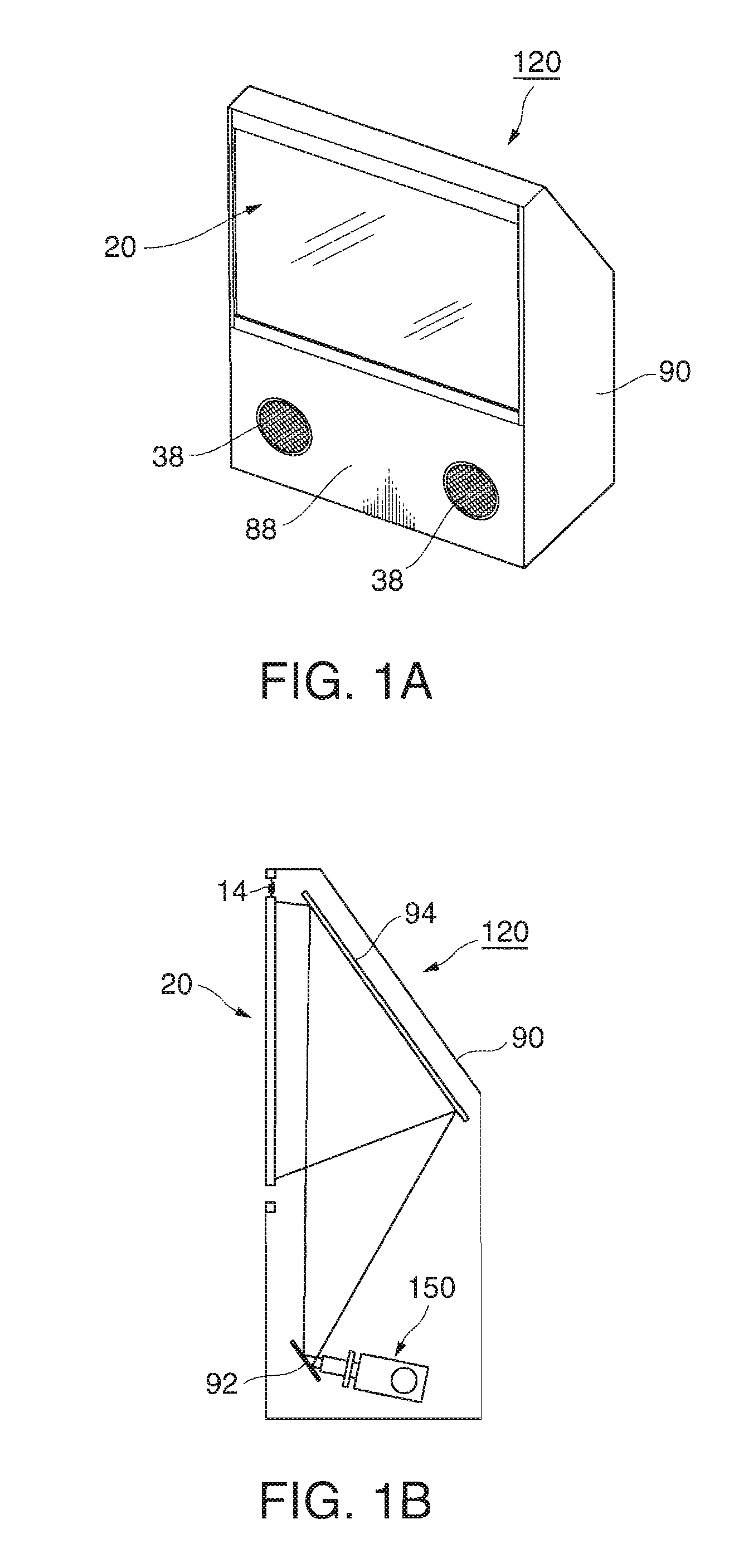
[0056]FIG. 1A is a perspective view illustrating a schematic structure of a rear projector 120 according to an embodiment of the invention. FIG. 1B is a side cross-sectional view illustrating the rear projector 120 shown in FIG. 1A. In the rear projector 120 according to this embodiment, light emitted from a light source is modulated by a light modulating unit, and the modulated light is projected onto a screen 20 to be diffused.
[0057]As shown in FIG. 1A, the rear projector 120 includes the screen 20 onto which an image is projected, and a casing 90 that is mounted on a side of a rear surface of the screen 20. A front panel 88 is provided at a portion of the casing 90 below the screen 20, and openings 38 for out put ting a sound from a speaker are provided at left and right sides of the front panel 88.
[0058]Next, an inner structure of the casing 90 of the rear projector 120 will be described.
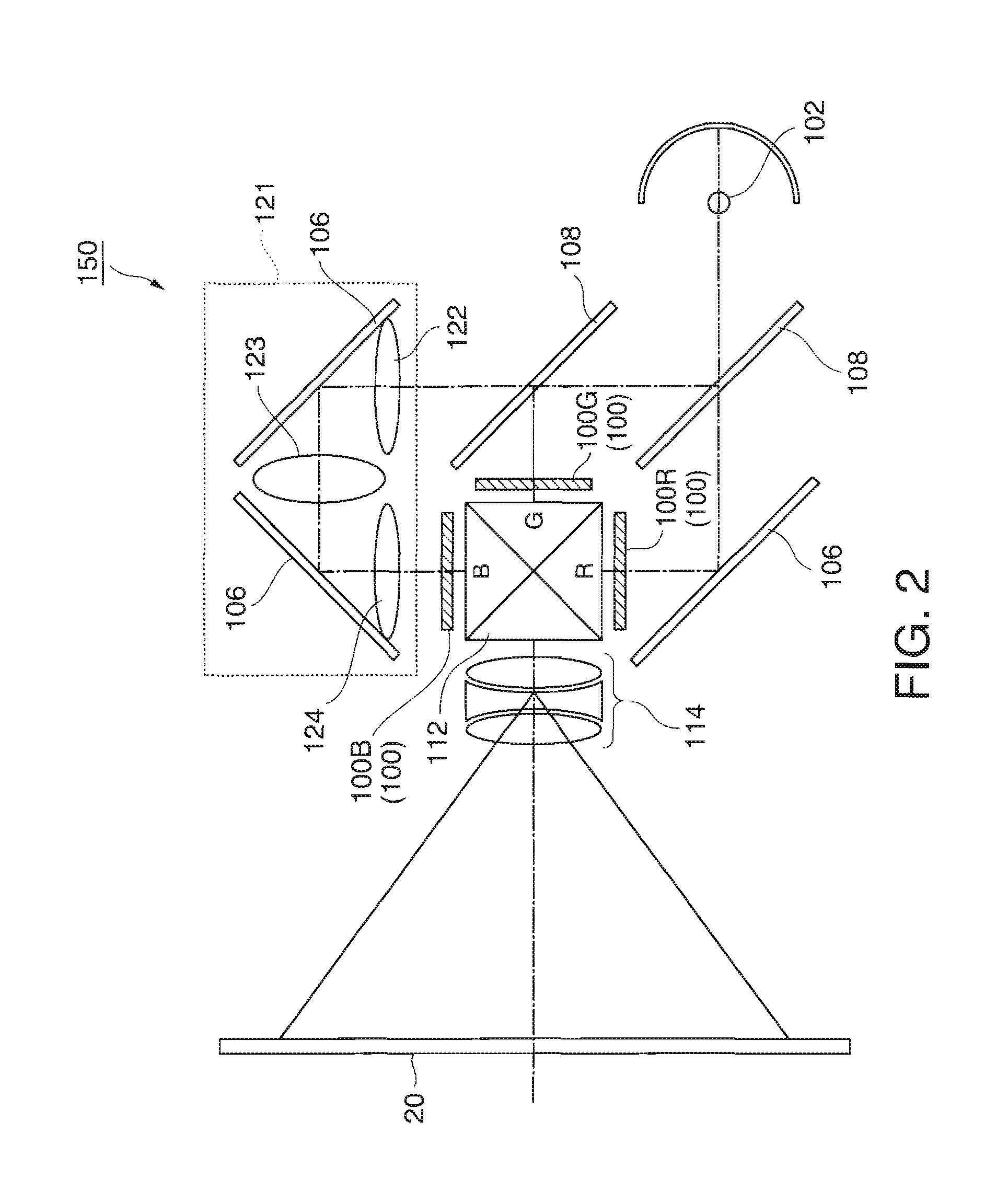
[0059]As shown in FIG. 1B, a projection optical system 150 is disposed on a lower side of an...
second embodiment
[0079]Next, a second embodiment of the invention will be described with reference to the accompanying drawings.
[0080]In the first embodiment, the diffusion plate suspends from the frame through the elastic members. However, in the second embodiment, a plurality of places of the diffusion plate are attached to the frame through the elastic members, different from the first embodiment. Further, since the other structure of the rear projector is the same as that of the first embodiment, the common constituent elements are denoted by the same reference numerals and the detailed description thereof is omitted.
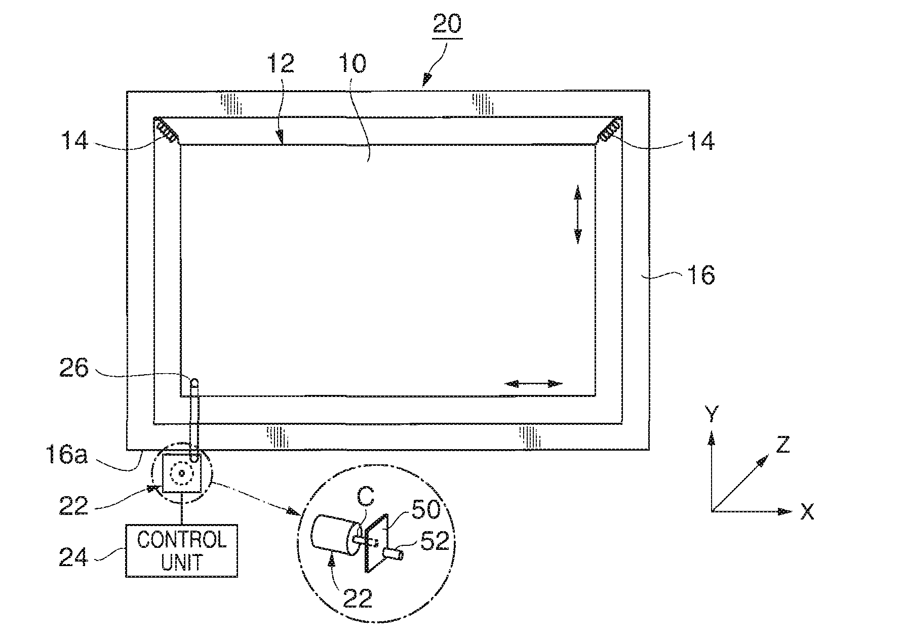
[0081]FIG. 4 is a plan view illustrating a schematic structure of a screen 20.
[0082]Rubber members 14 are disposed at equal intervals along the circumference of the diffusion plate 10, and the diffusion plate 10 is attached to the frame 16 through the rubber members 14. As a result, the diffusion plate 10 is elastically supported by means of the rubber members 14 that are inserted b...
third embodiment
[0086]Next, a third embodiment of the invention will be described with reference to the accompanying drawings.
[0087]In the second embodiment, one driving unit is mounted in the diffusion plate, but in the third embodiment, a plurality of driving units are mounted in the diffusion plate, different from the second embodiment. Further, since the other structure of the rear projector is the same as that of the first embodiment, the common constituent elements are denoted by the same reference numerals and the detailed description thereof is omitted.
[0088]FIG. 5 is a plan view illustrating a schematic structure of a screen 20.
[0089]Rubber members 14 are disposed at equal intervals along the circumference of the diffusion plate 10, and the diffusion plate 10 is attached to the frame 16 through the rubber members 14. As a result, the diffusion plate 10 is elastically supported by means of the rubber members 14 that are inserted between the diffusion plate 10 and the frame 16, and the diffu...
PUM
 Abstract
Description
Claims
Application Information