Changing the scrambling code of a base station for wireless telecommunications

a wireless telecommunications and base station technology, applied in the field of wireless telecommunications, can solve problems such as dropped calls and lost coverag

Inactive Publication Date: 2008-02-14
LUCENT TECH INC
View PDF19 Cites 92 Cited by
  • Summary
  • Abstract
  • Description
  • Claims
  • Application Information

AI Technical Summary

Benefits of technology

[0005]The inventors found a way to the change the scrambling code used by

Problems solved by technology

Unfortunately, this procedure causes a p

Method used


Image

  • Changing the scrambling code of a base station for wireless telecommunications
  • Changing the scrambling code of a base station for wireless telecommunications
  • Changing the scrambling code of a base station for wireless telecommunications

Examples


Embodiment Construction

[0019]When considering a known system, the inventors realised that it should be possible to identify a need for a change in scrambling code, then select a new scrambling code and implement its use, in an automated procedure without requiring a human operator to effect the scrambling code change.

[0020]A first example will now be described in detail.

The Network

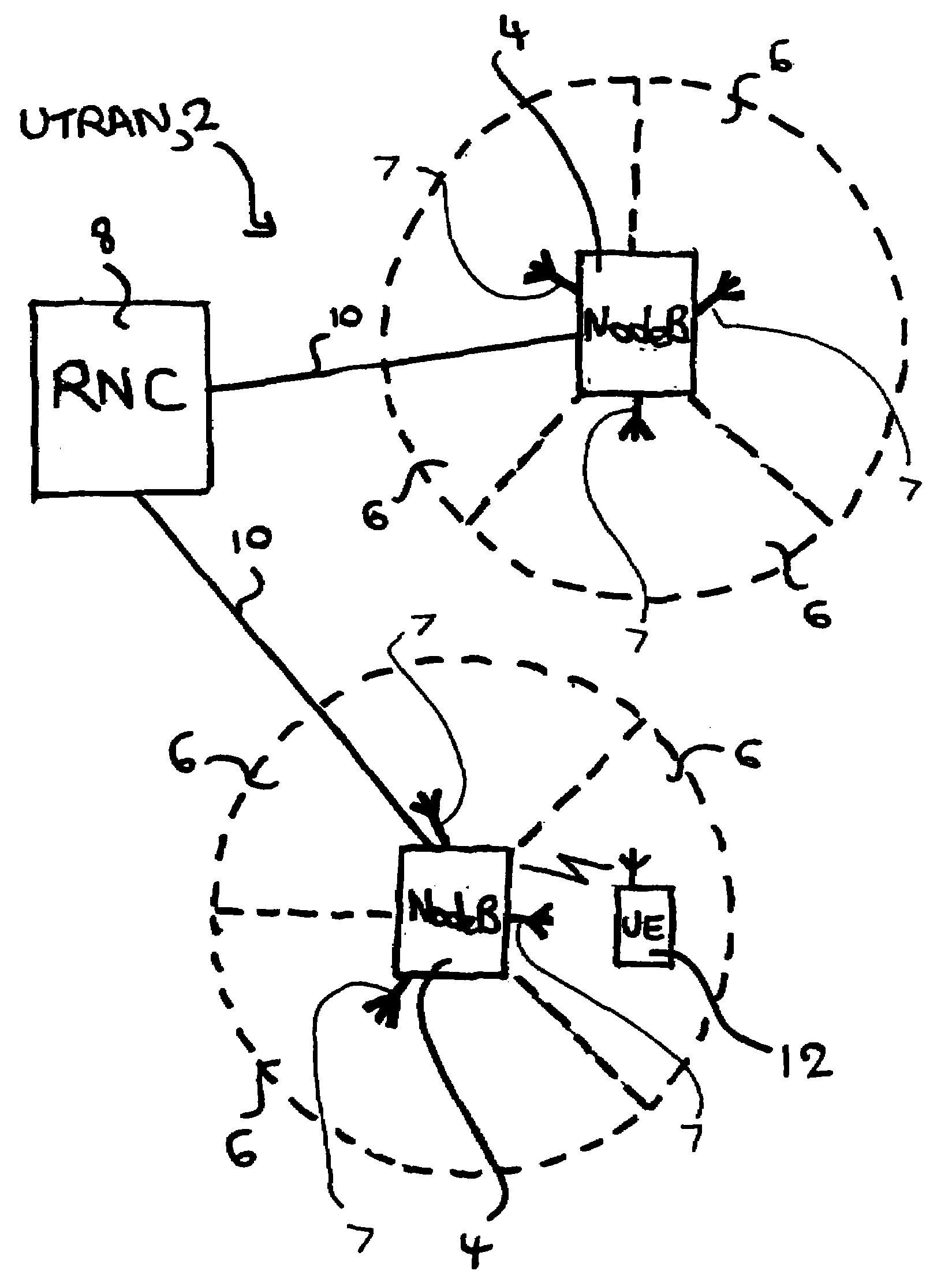
[0021]An example network is a Universal Mobile Telecommunications System (UMTS) terrestrial access network (UTRAN), which is a type of wideband code division multiple access (CDMA) network for mobile telecommunications. The UTRAN network is basically as shown in FIG. 1. Only one radio network controller and two base stations of the UTRAN network 2 are shown for simplicity. As shown in this Figure, the UTRAN network 2 includes base stations 4. In the Figure, each of the base stations 4 is also designated “Node B” in accordance with UMTS terminology. A cell, also referred to as a sector, is the radio-coverage area served by a corr...


PUM


Abstract

A method is provided of a base station for wireless telecommunications changing scrambling code to be applied to pilot signals for transmission. The method comprises automatically:
    • identifying a need to change scrambling code,
    • selecting a new scrambling code for use,
    • reprogramming the base station to use the scrambling code, and
    • using the new scrambling code for subsequent pilot signal transmissions.

Description

FIELD OF THE INVENTION[0001]The present invention relates to telecommunications, in particular to wireless telecommunications.DESCRIPTION OF THE RELATED ART[0002]There are wireless telecommunications systems based on code division multiple access, such as those compliant with the Universal Mobile Telecommunications System (UMTS) standard. Particularly in such systems, neighbouring base stations apply distinctive scrambling codes to some of their messages to mobile terminals. A mobile terminal is informed of the range of possible scrambling codes to expect, and then identifies a base station using one of those scrambling codes as being the one from which the mobile terminal is to receive and decode signals.[0003]To minimise interference of one base station with another, and prevent identification problems, the scrambling code used by a base station should be different from that of neighbouring base stations, including any base stations with which there might be coverage area overlap....

Claims


Application Information

Patent Timeline
IPC IPC(8): H04B1/38H04M1/00H04W16/10H04W48/08H04W72/04H04W88/08
CPCH04B2201/70701H04B2201/70702H04J13/10H04W16/10H04W36/08H04W88/08H04W72/02H04L1/0001H04W48/08
Inventor CLAUSSEN, HOLGERSAMUEL, LOUIS GWYN
Owner LUCENT TECH INC
Why Eureka
Try Eureka