
Wearable Pulse Wave Velocity Blood Pressure Sensor and Methods of Calibration Thereof

a pulse wave velocity and blood pressure sensor technology, applied in the field of wearable pulse wave velocity blood pressure sensor and methods of calibration thereof, can solve the problems of no optimal solution for truly wearable nibp measurement, no optimal solution for realizing true non-invasive blood pressure (nibp) measurement, and device bulkyness

Inactive Publication Date: 2008-02-14
MASSACHUSETTS INST OF TECH
View PDF27 Cites 336 Cited by
  • Summary
  • Abstract
  • Description
  • Claims
  • Application Information

AI Technical Summary

Benefits of technology

[0024] In alternate embodiments of the invention, the output circulatory metric may be an arterial blood pressur

Problems solved by technology

However, a significant challenge to realizing true non-invasive blood pressure (NIBP) measurement remains the problem of accounting for the unknown tension in the underlying arterial wall: If one simply measures pressure external to an artery (for instance, on the overlying skin), one is measuring the balance of intra-arterial pressure and the rapidly varying arterial wall tension.
Yet, there is no optimal solution to truly wearable NIBP measurement.
While they are the standard-of-care, such devices nonetheless have shortcomings, including: (i) their circumferential compression of the extremity is uncomfortable, causing bruising or interrupting sleep; (ii) they are very susceptible to motion, since motion artifact cannot be distinguished from arterial volume pulsations, (iii) they are not readily miniaturizable so the device tends to be bulky, and (iv) overall, their accuracy versus a gold-standard is often inadequate.
A more convenient version of the oscillometric cuff fits on the wrist, but measurement errors can arise if (v) the wrist is at a different vertical level from the heart, or (vi) if the patient has distal arterial fixed occlusions or vasospasm.
The Vasotrac Device and “Reverse Oscillometry”: MedWave's BP sensor places a small “balloon” over the radial artery, increases the external pressure applied to the underlying radial artery, and measures the volumetric pulsations in the “balloon.” It is therefore a variation of standard oscillometry, and the company describes the methods as “reverse oscillometry.” The device is unsuitable for ambulatory monitoring because of its size and power requirements, moreover, it is motion-sensitive, like other oscillometric methods.
In numerous instances, published works may refer to this measurement modality as ‘photoplethysmography’, although such usage is imprecise, and it can leave the incorrect impression that the PPG and arterial blood pressure (ABP) signals are interchangeable.
Yet it requires a bulky, power-thirsty actuation system to drive the pneumatic cuff.
Raising and lowering the arms changes the hydrostatic pressure within the extremity, so PWV may be unreliable in any position except supine.
PWV is distance divided by pulse transit time, but it is difficult to measure the distance accurately, or keep the distance constant.
But the electrocardiogram (ECG) is a problematic marker of pulse onset, perhaps in part because of variable electromechanical delays.
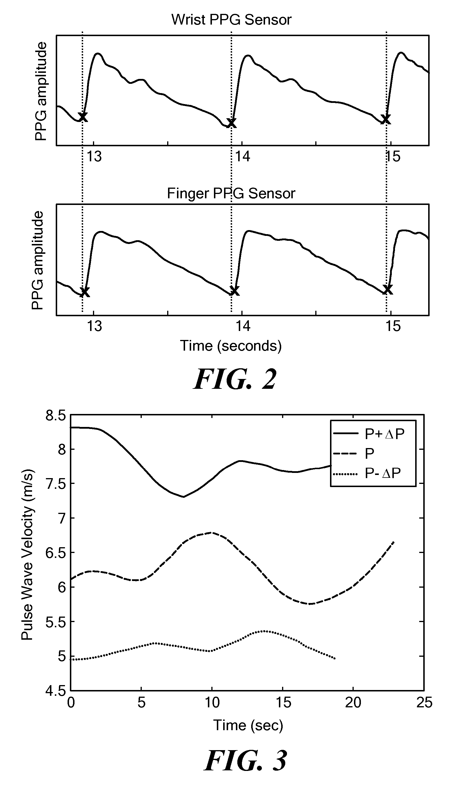
The fact that PPG measurements require the use of two distinct PPG sensors has also proven problematic.
Arterial tonometer solutions: Tonometers are very difficult to use, even in controlled laboratory conditions, and thus they have no role in ambulatory blood pressure measurement.
These conditions are so difficult to achieve in practice that the one commercially available tonometer comes with a separate oscillometric cuff to calibrate the unreliable (in terms of absolute arterial pressure) tonometer unit.

Method used


Image

  • Wearable Pulse Wave Velocity Blood Pressure Sensor and Methods of Calibration Thereof
  • Wearable Pulse Wave Velocity Blood Pressure Sensor and Methods of Calibration Thereof
  • Wearable Pulse Wave Velocity Blood Pressure Sensor and Methods of Calibration Thereof

Examples


Embodiment Construction

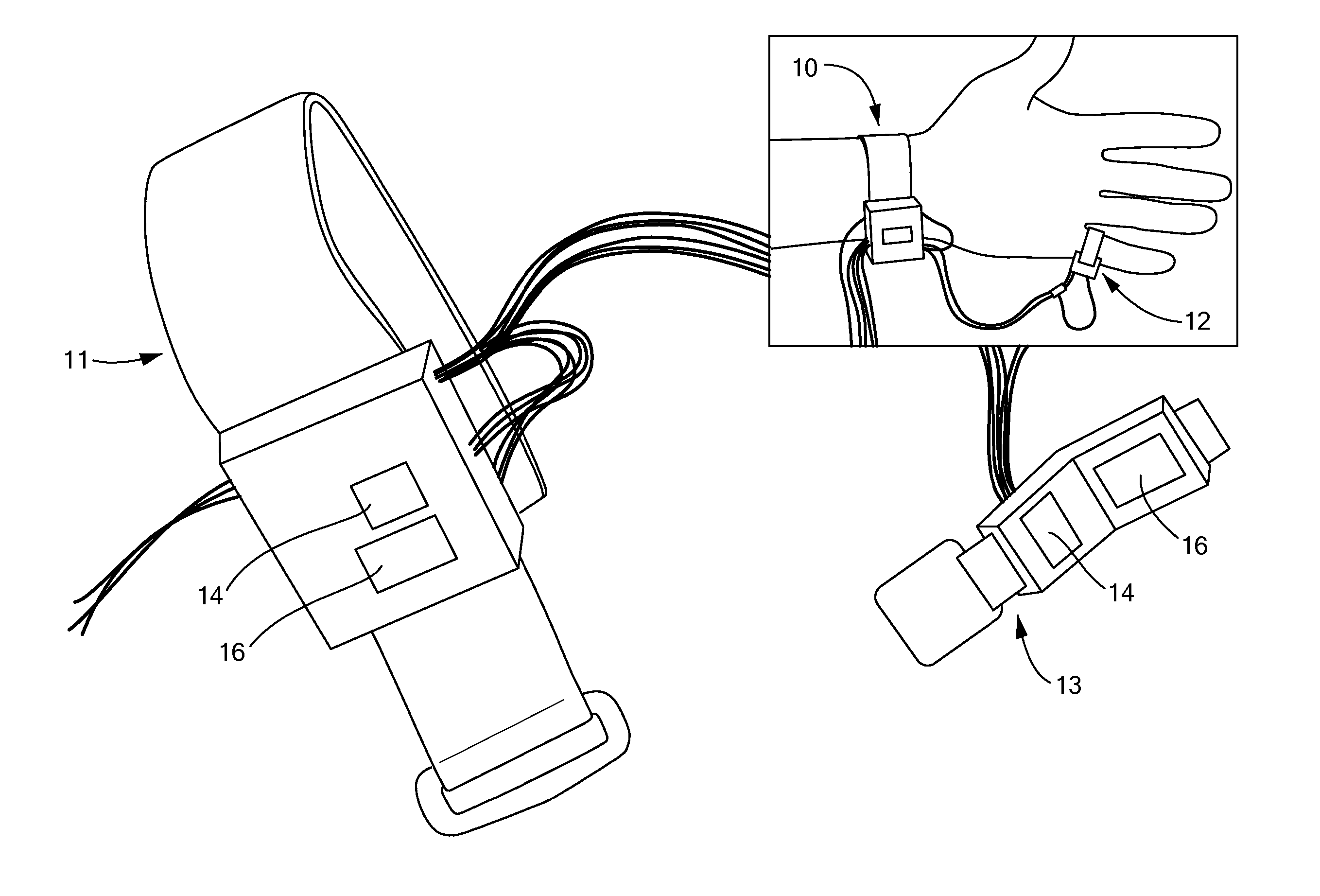
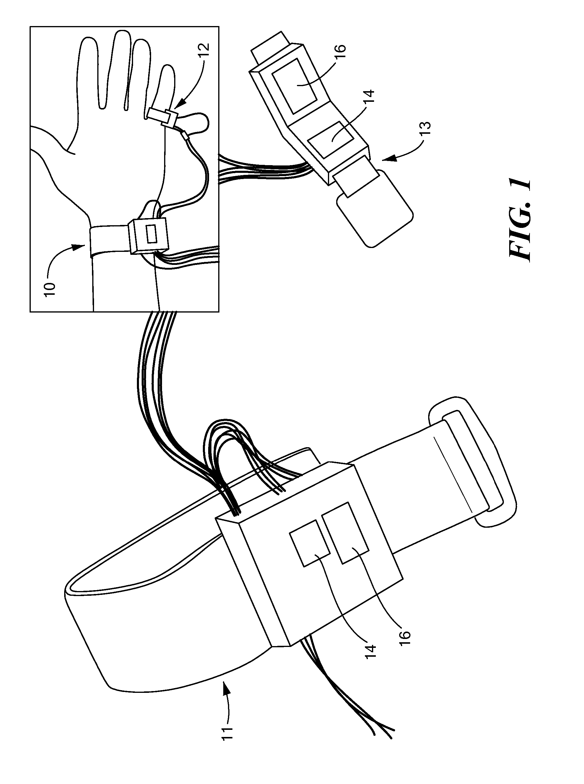
[0046] In accordance with preferred embodiments of the present invention, a novel wearable device is described for monitoring blood pressure. Blood pressure is one example of an output circulatory metric that is of great clinical value. One embodiment of the invention uses the well-established principle that pulse transmission time (PTT) in an artery depends on blood pressure. In this case, PTT is an example of an “input circulatory metric” that may more readily be obtained by measurement than the blood pressure, which is of greater clinical value. This approach is, in theory, appealing because it does not require any squeezing or other discomforts associated with typical cuff-based devices. Yet, in the past, PTT-based methods have proven less reliable than desirable because compliance (and, hence, PTT) in an artery also changes for reasons other than blood pressure, as discussed above.

[0047] As used herein, and in any appended claims, the term “blood pressure” shall be taken to re...


PUM


Abstract

An apparatus and methods for performing a circulatory measurement on an extremity, such as a hand, of a subject. The circulatory measurement results in the derivation of an output circulatory metric that may encompass blood pressure or various other circulatory metrics. An indicator of an input circulatory metric at a locus on the extremity is measured, such as a pulse transit time. To determine the pulse transit time, a first plethysmographic signal may be obtained at a first position on the extremity, while a second plethysmographic signal may be obtained at a second position on the extremity of the subject. A transit time characterizing a circulatory pressure wave is calculated based on the first and second plethysmographic signals, leading to derivation of a wave speed. A calibration is then applied to provide the circulatory measurement based at least on the derived wave speed and a measured indicator of a hydrostatic component of blood pressure. Calibration is provided, in certain described embodiments, by derivation of two calibration parameters, a gain and a pulse transit time at zero pressure. Methods for deriving the calibration parameters include performing measurements under distinct hydrostatic pressure conditions, and based upon a measured derivative with respect to pressure of the pulse wave velocity.

Description

[0001] The present application is a continuation-in-part of U.S. patent application Ser. No. 11 / 508,123, filed Aug. 22, 2006, and, like that application, claims the priority of U.S. Provisional Patent Application Ser. No. 60 / 710,085, filed Aug. 22, 2005. Additionally, the present application claims the priority of U.S. Provisional Patent Application Ser. No. 60 / 822,832, filed Aug. 18, 2006. All of the foregoing applications are incorporated herein by reference.TECHNICAL FIELD [0002] The present invention relates to methods and apparatus for measuring arterial blood pressure at an extremity of a subject, and more particularly, to methods and apparatus based upon wave velocity measured between the locations of two photoplethysmographic sensors disposed on an extremity of a subject. BACKGROUND OF INVENTION [0003] It is well recognized that ambulatory blood pressure (BP) monitoring by means of wearable sensors has the potential to enable new levels of health-related vigilance and medica...

Claims


Application Information

Patent Timeline
IPC IPC(8): A61B5/022
CPCA61B5/02125A61B5/7239A61B5/02255
Inventor MCCOMBIE, DEVIN B.REISNER, ANDREW T.ASADA, HARUHIKO H.SHALTIS, PHILLIP
Owner MASSACHUSETTS INST OF TECH
Learn More