Firearm system for data acquisition and control

a data acquisition and control and firearm technology, applied in the field of firearms, can solve the problems of not being convenient to locate, not being able to notify the user as to how, and requiring additional equipmen

Inactive Publication Date: 2008-02-14
MCRAE MICHAEL WILLIAM
View PDF31 Cites 208 Cited by
  • Summary
  • Abstract
  • Description
  • Claims
  • Application Information

AI Technical Summary

Benefits of technology

[0051] The invention consists of a central microprocessor unit. This microprocessor collects information from various sensors and accessories that are mounted on the firearm. The microprocessor also receives input from the user by way of control buttons and/or keypad. The microprocessor may interpret the sensory input to indicate certain conditions of the firearm. Such as “empty chamber”, “action-open”, “safety off”, “bullet velocity”, “shot fired”, “range to target”, et cetera. The microprocessor may

Problems solved by technology

Additionally, the firearm system could notify the user as to how many rounds are available in the firearm.
However this requires additional equipment to be purchased and set-up by the user, and is not conveniently located in or on the firearm itself.
However, this device fails to have a built-in range finder and thus not only requires an additional piece of equipment, but the user must enter the range information into the device.
However, the device fails to take into account the ballistic coefficient of

Method used


Image

  • Firearm system for data acquisition and control
  • Firearm system for data acquisition and control
  • Firearm system for data acquisition and control

Examples


Embodiment Construction

—FIGS. 1 THROUGH 15

[0075]FIG. 1 through FIG. 15 depict specific preferred embodiments of the present invention for purposes of illustration only. One skilled in the art will recognize from the following discussion that alternative embodiments of the structures and methods illustrated herein may be employed without departing from the invention.

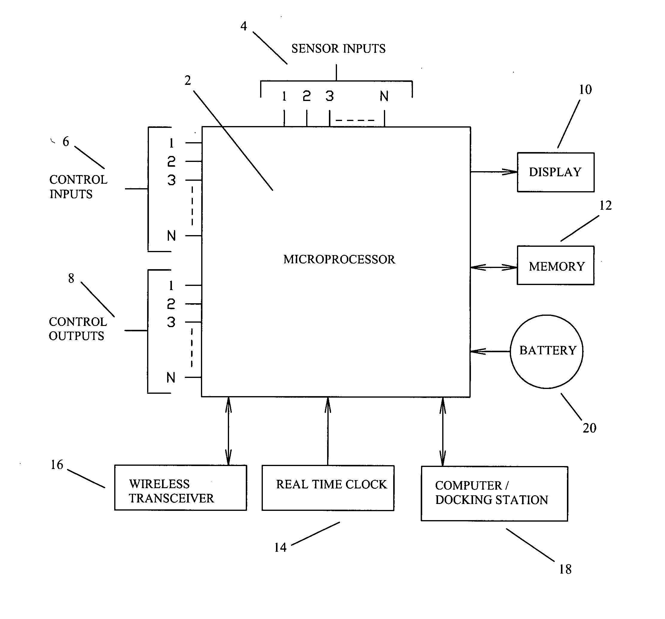
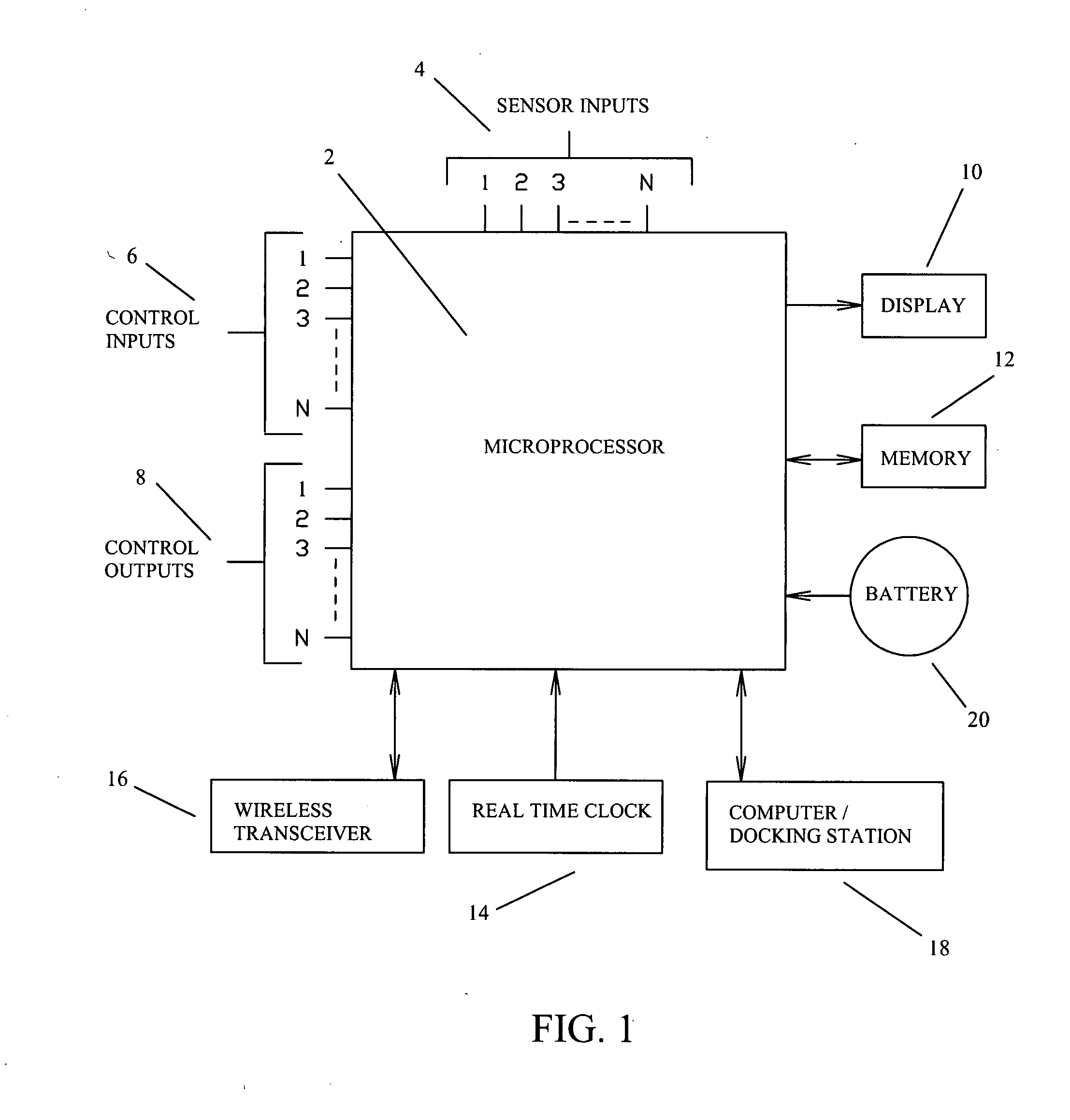
[0076] Now referring to FIG. 1; This diagram depicts a typical architecture of the firearm system. The focal point of the architecture is the microprocessor 2. Here the microprocessor communicates with and / or controls the firearm system. The microprocessor receives sensory data through sensor inputs 4. The sensors associated with these inputs are located on the firearm itself, and will be discussed in later figures. The microprocessor will also receive user data and commands through control inputs 6. These inputs may come from buttons, knobs, or keypads that are also located on the firearm itself. The microprocessor may also be equipped with a...


PUM


Abstract

A microprocessor circuit that is used to monitor and control a firearm. The microprocessor circuit accomplishes this by monitoring various sensor & control inputs, and acting on these inputs to execute user defined functions. The microprocessor circuit can use the sensory input to determine firearm statistics. These statistics can include the number of times the firearm has been shot, the efficiency of the firearm automatic action, range-to-target, and et cetera. The firearm system can also use a combination of sensors to fabricate a bullet chronograph whereby the muzzle velocity of a cartridge can be determined. These statistics can be date-stamped and recorded into memory. Statistics from Law Enforcement firearms can be used for courtroom evidence and police reporting. These statistics can also be used for firearm maintenance and warranty repair. The microprocessor circuit can display the statistical data to the user via simple light emitting diodes, or sophisticated liquid crystal displays. Data can also be downloaded to a computer docking station as well. The microprocessor circuit can also display the information within the optics of a riflescope. When used in conjunction with a laser range finder sensor, the microprocessor circuit can adjust the electronic cross-hairs (reticle) to compensate for the bullet trajectory.

Description

CROSS-REFERENCE TO RELATED APPLICATIONS [0001] This application claims the benefit of Provisional Patent Application; [0002] Ser. No.: 60 / 802,677 [0003] Filed: May 23, 2006 [0004] Atty Docket: MCRAE-SEFEDERALLY SPONSORED RESEARCH [0005] Not Applicable SEQUENCE LISTING OR PROGRAM [0006] Not Applicable BACKGROUND OF THE INVENTION [0007] 1. Field of Invention [0008] This invention relates to firearms; specifically to an electronic system for gathering firearm data, manipulating such data, displaying data to the user, receiving commands from the user, recording pertinent information to memory, and finally for controlling the firearm itself. [0009] 2. Description of Prior Art [0010] Firearms are used for self-defense, hunting, marksmanship competition, law enforcement, and the military. Although the field of firearms is very mature, modern electronics now provide a way to expand the field of firearms even further. [0011] In much the same way that a car's computer interfaces with the user...

Claims


Application Information

Patent Timeline
IPC IPC(8): G06F17/00F41G1/00G01C3/00H04B1/38H04L9/00G06F3/01G06F13/14
CPCF41A17/06F41G1/38F41A9/53G06F1/1632G01S17/88
Inventor MCRAE, MICHAEL WILLIAM
Owner MCRAE MICHAEL WILLIAM
Why Eureka
Try Eureka