Methods and apparatus for control using control devices that provide a virtual machine environment and that communicate via an IP network
What is AI technical title?
AI technical title is built by Patsnap AI team. It summarizes the technical point description of the patent document.
a virtual machine environment and control device technology, applied in the field of control systems, can solve the problems of increasing pressure and boiling activity, and less uniform command and operation of control devices, and achieve the effects of confusion, complexity and cost reduction, and removing incentives for product differentiation
Inactive Publication Date: 2008-02-14
SCHNEIDER ELECTRIC SYST USA INC
View PDF99 Cites 80 Cited by
Summary
Abstract
Description
Claims
Application Information
AI Technical Summary
This helps you quickly interpret patents by identifying the three key elements:
Problems solved by technology
Method used
Benefits of technology
Benefits of technology
[0006] Controllers generate settings for the control devices based on measurements from sensor type field devices. Controller operation is typically based on a “control algorithm” that maintains a controlled system at a desired level, or drives it to that level, by minimizing differences between the values measured by the sensors and, for example, a setpoint defined by the operator.
[0016] Further objects of the invention are to provide such methods and apparatus as reduce the confusion, complexity and costs attendant to prior art control systems.
[0018] Still further objects of the invention are to provide such methods and apparatus as achieve confusion-, complexity- and cost-reduction without hampering manufacturer creativity and without removing incentives to development of product differentiators. SUMMARY OF THE INVENTION
Problems solved by technology
If the vessel pressure is too low, the control algorithm may call for incrementally opening the heating gas valves, thereby, driving the pressure and boiling activity upwards.
Efforts such as this have been limited to specific segments of the control hierarchy (e.g., bus communications among field devices) and are typically hampered by technological changes that all to soon render the standards obsolete.
Still less uniform are the command and operation of control devices.
Method used
Image
Click on the blue label to locate the original text in one second.
Reading with bidirectional positioning of images and text.
Examples
Embodiment Construction
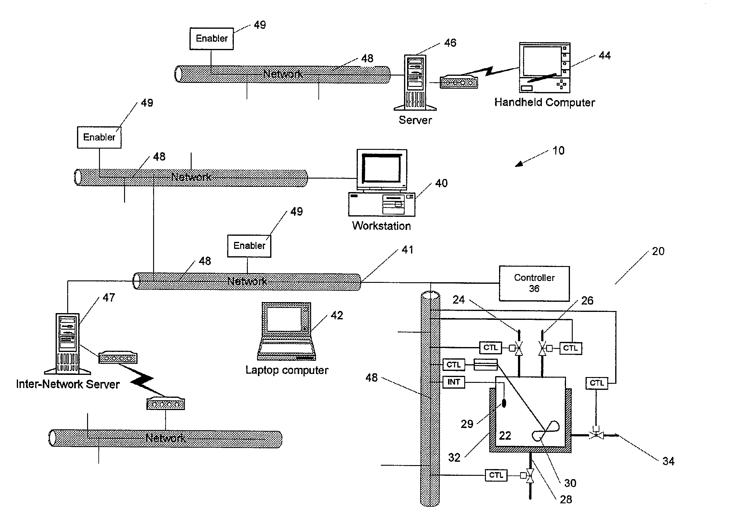
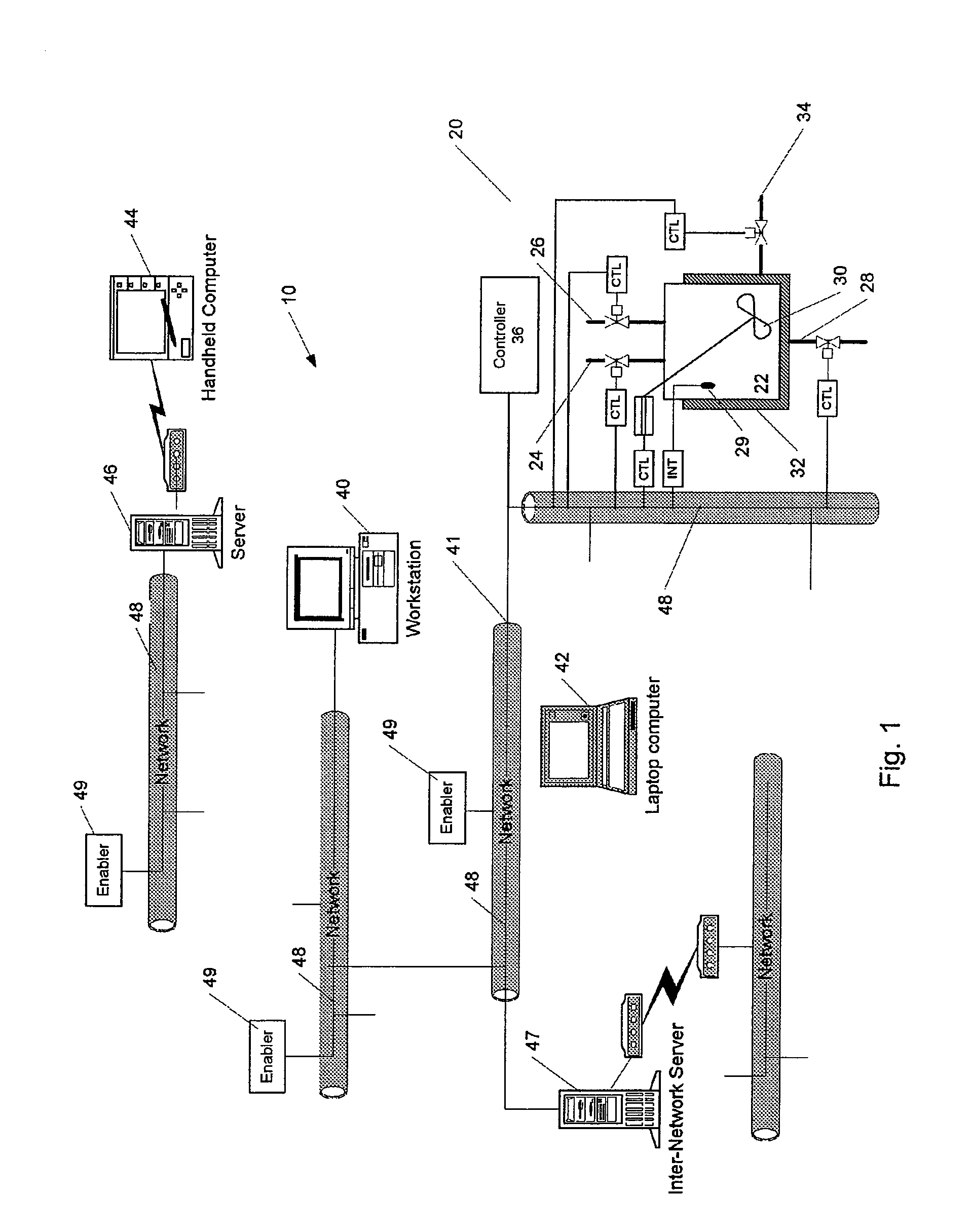
[0035]FIG. 1 depicts a process control system 10 according to the invention. The system includes networked control devices that monitor and control a hypothetical mixing process that utilizes mixing chamber 22, fluid inlets 24, 26, fluid outlet 28, paddle 30, cooler 32, and cooler inlet 34. Though illustrated and described below for use in connection with process control, those skilled in the art will appreciate that apparatus and methods according to the invention can be used in connection any industrial, manufacturing, service, environmental or other process, device or system amenable to monitoring or control (hereinafter, collectively, “control”).
[0036] The networked control devices include actuators, such as the valves depicted as controlling inlets and outlets 24-28 and 34. A further actuator is shown controlling paddle 30. These and other actuators utilized by the control system are constructed and operated in the conventional manner, as modified in accord with the teachings ...
PUM
Abstract
The invention provides improved methods and apparatus for control using field and control devices that provide a virtual machine environment and that communicate via an IP network. By way of non-limiting example, such field device can be an “intelligent” transmitter or actuator that includes a low power processor, along with a random access memory, a read-only memory, FlashRAM, and a sensor interface. The processor can execute a real-time operating system, as well as a Java virtual machine (JVM). Java byte code executes in the JVM to configure the field device to perform typical process control functions, e.g., for proportional integral derivative (PID) control and signal conditioning. Control networks can include a plurality of such field and control devices interconnected by an IP network, such as an Ethernet.
Description
BACKGROUND OF THE INVENTION [0001] This application claims the priority of the following United States Patent Applications: U.S. Patent Application Ser. No. 60 / 139,071, entitled OMNIBUS AND WEB CONTROL, filed Jun. 11, 1999; U.S. Patent Application Ser. No. 60 / 144,693, entitled OMNIBUS AND WEB CONTROL, filed Jul. 20, 1999; U.S. Patent Application Ser. No. 60 / 149,276, entitled METHODS AND APPARATUS FOR PROCESS CONTROL (“AUTOARCHITECTURE”), filed Aug. 17, 1999; U.S. patent application Ser. No. 09 / 345,215, entitled PROCESS CONTROL SYSTEM AND METHOD WITH IMPROVED DISTRIBUTION, INSTALLATION, AND VALIDATION OF COMPONENTS, filed Jun. 30, 1999.[0002] The invention pertains to control systems and, more particularly, to methods and apparatus for networking, configuring and operating field devices, controllers, consoles and other control devices. [0003] The terms “control” and “control systems” refer to the control of a device or system by monitoring one or more of its characteristics. This is ...
Claims
Application Information
Patent Timeline
Application Date:The date an application was filed.
Publication Date:The date a patent or application was officially published.
First Publication Date:The earliest publication date of a patent with the same application number.
Issue Date:Publication date of the patent grant document.
PCT Entry Date:The Entry date of PCT National Phase.
Estimated Expiry Date:The statutory expiry date of a patent right according to the Patent Law, and it is the longest term of protection that the patent right can achieve without the termination of the patent right due to other reasons(Term extension factor has been taken into account ).
Invalid Date:Actual expiry date is based on effective date or publication date of legal transaction data of invalid patent.
Patent Type & AuthorityApplications(United States)

