Resonator device at junction of combustor and combustion chamber

a combustor and combustion chamber technology, applied in the field of resonators, can solve the problems of sympathetic vibration, near-by structures to vibrate and ultimately break, and the effect of reducing the efficiency of the combustion chamber

Inactive Publication Date: 2008-02-21
SIEMENS ENERGY INC
View PDF34 Cites 60 Cited by
  • Summary
  • Abstract
  • Description
  • Claims
  • Application Information

AI Technical Summary

Problems solved by technology

If these pressure oscillations, which are sometimes referred to as combustion dynamics, reach a certain amplitude they may cause nearby structures to vibrate and ultimately break.
A particularly undesired situation is when a combustion-generated acoustic wave has a frequency at or near the natural frequency of a component of the gas turbine engine.
Such adverse synchronicity may result in sympathetic vibration and ultimate breakage or other failure of such component Various modifications of and devices for the combustion section of a gas turbine engine have been developed to address the problem of combustion-generated acoustic waves.

Method used


Image

  • Resonator device at junction of combustor and combustion chamber
  • Resonator device at junction of combustor and combustion chamber
  • Resonator device at junction of combustor and combustion chamber

Examples


Embodiment Construction

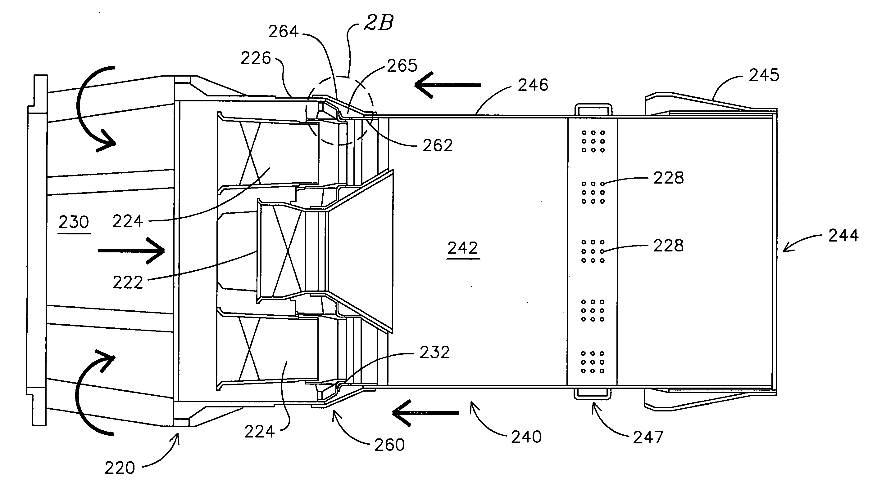
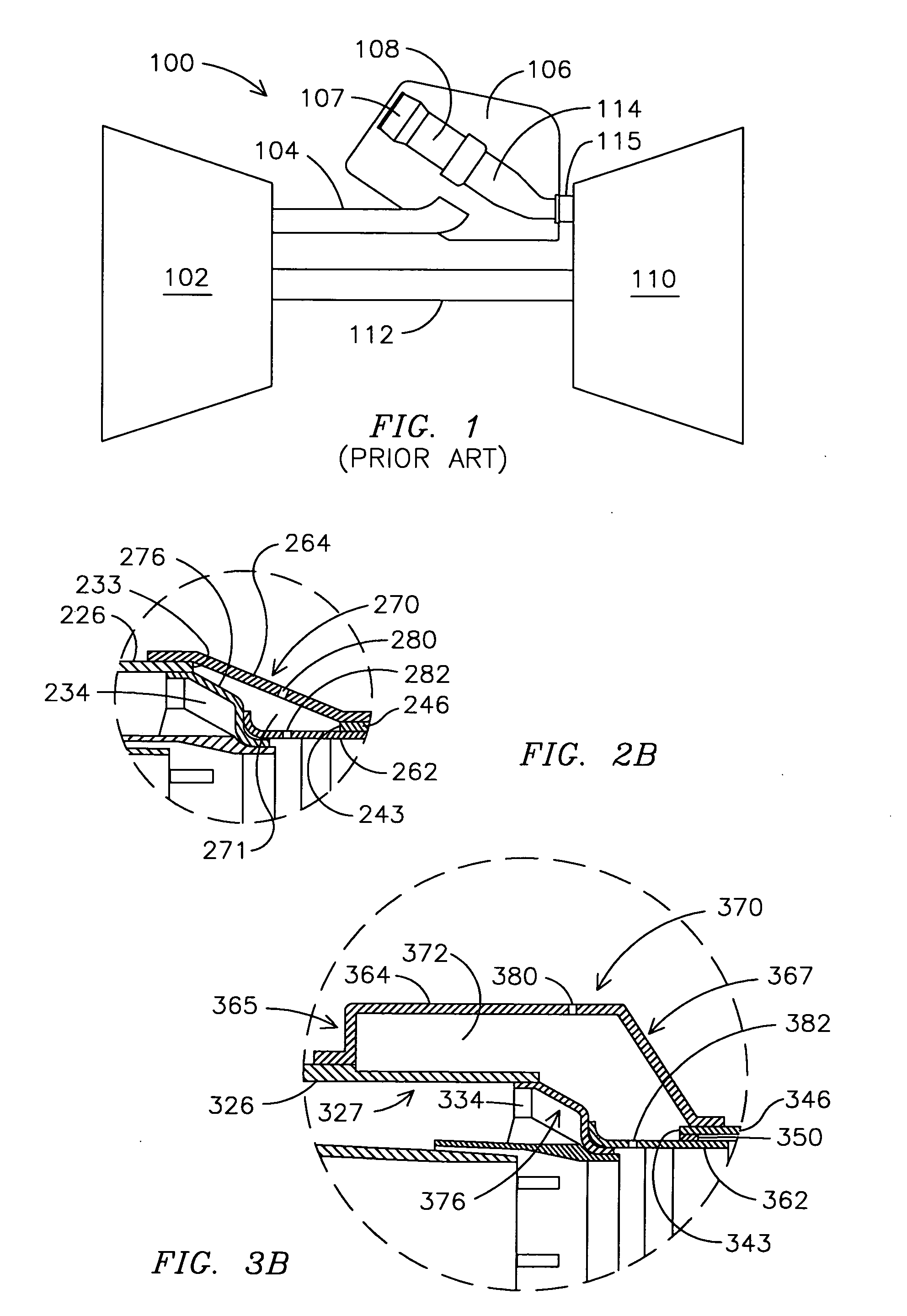
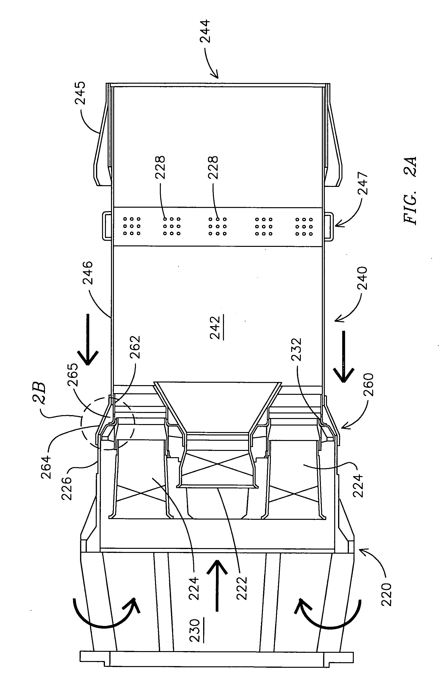
[0016]Embodiments of the invention provide a number of advances over known arrangements and designs of acoustic dampers for combustors. The various embodiments provide a plurality of separate resonator chambers at a junction of a combustion chamber and a combustor. The combustor typically is defined externally by a combustor housing that meets the combustion chamber to form the junction. Resonator chambers at this junction, in various embodiments, are designed and tuned to damp two or more undesired acoustic frequencies of interest that are generated during combustion operations. Given that this position is more upstream of the areas of maximum combustion, and far less subject to a risk of hot gas ingestion than more downstream-located resonators, there is greater flexibility with regard to flow design. This provides opportunities for improved resonator damping efficiency and for narrower targeting of frequencies to damp. This is because less inflow is required to prevent incursion ...


PUM


Abstract

One or more Helmholtz-type resonators (270) is / are provided at the junction (260) of a combustor (220) and a combustion chamber (240) of a gas turbine engine (100). In one embodiment, adjacent Helmholtz-type resonators (290, 291, 292), which may be separated by respective baffles (285), have different volumes that help provide for damping different undesired combustion-generated acoustic pressure waves. In some embodiments, a structural member (435) may be provided between adjacent Helmholtz-type resonators (425, 426, 427, 428) at the junction. At least one of the plurality of Helmholtz-type resonators comprises one or more inlet openings (480), and one or more exit openings (482). Embodiments (370, 425-429) are described in which Helmholtz-type resonators provided at the junction are enlarged in size using various approaches. The positioning at the junction, upstream of the space (242) in which combustion occurs, and providing a plurality of differently sized resonators, provides for improved flexibility and resonator damping efficiencies.

Description

FIELD OF INVENTION[0001]The invention generally relates to a gas turbine engine, and more particularly to a resonator positioned at a junction of a combustor and a mating combustion chamber of a can-annular gas turbine engine.BACKGROUND OF THE INVENTION[0002]Combustion engines such as gas turbine engines are machines that convert chemical energy stored in fuel into mechanical energy useful for generating electricity, producing thrust, or otherwise doing work. These engines typically include several cooperative sections that contribute in some way to this energy conversion process. In gas turbine engines, air discharged from a compressor section and fuel introduced from a fuel supply are mixed together and burned in a combustion section. The products of combustion are harnessed and directed through a turbine section, where they expand and turn a central rotor.[0003]A variety of combustor designs exist, with different designs being selected for suitability with a given engine and to a...

Claims


Application Information

Patent Timeline
Patent Type & Authority Applications(United States)
IPC IPC(8): F02C7/24
CPCF23R3/286F23M20/005F23R2900/00014F23R3/343
Inventor JOHNSON, CLIFFORD E.WASIF, SAMER P.
Owner SIEMENS ENERGY INC
Why Eureka
Try Eureka