Single-piece cooling blocks for casting and molding

a single-piece cooling block and casting technology, applied in casting apparatus, melt-holding vessels, manufacturing tools, etc., can solve the problems of multiple manufacturing steps, failure potential of joints between pieces, and the need for additional time and money to complete conventional cooling blocks

Inactive Publication Date: 2008-02-21
DUBAY RICHARD L
View PDF26 Cites 5 Cited by
  • Summary
  • Abstract
  • Description
  • Claims
  • Application Information

AI Technical Summary

Problems solved by technology

Thus, the joints between the pieces produce a potential for failure during the manufacturing process.
Conventional c

Method used


Image

  • Single-piece cooling blocks for casting and molding
  • Single-piece cooling blocks for casting and molding
  • Single-piece cooling blocks for casting and molding

Examples


Embodiment Construction

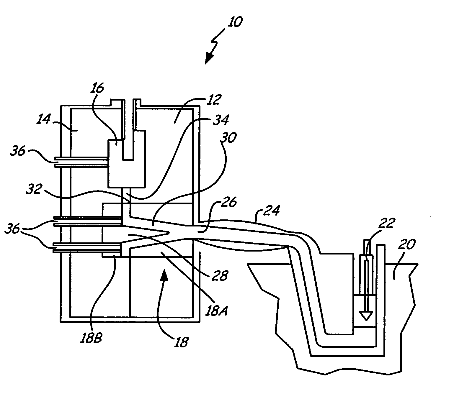
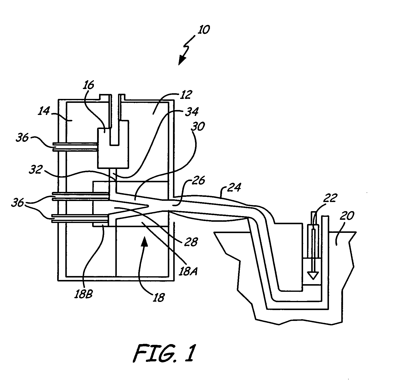
[0014]FIG. 1 shows a sectional view of die casting system 10 in which the present invention is used. The invention is typically used in zinc or magnesium hot chamber die casting operations, and the invention is hereinafter described in reference to die casting. In other embodiments, however, the present invention can also be used in cold chamber die casting operations, or injection molding applications. Die casting system 10 includes stationary die half 12 and moving die half 14. Stationary die half 12 and moving die half 14 together comprise mold cavity 16, which has the shape of an object that can be molded with die casting system 10. Die casting system 10 also includes cooling blocks 18A and 18B (collectively referred to as cooling block 18 when assembled), which are used to control the flow of molten metal into die cavity 16. Molten metal from crucible 20 is injected with piston 22 into die casting system 10 through nozzle 24 and sprue 26 of cooling block 18A. As molten metal en...


PUM

PropertyMeasurementUnit
Temperatureaaaaaaaaaa
Lengthaaaaaaaaaa
Circumferenceaaaaaaaaaa

Abstract

A block for use in a die casting or molding system receives manufacturing material for distribution into a runner system of a die or mold and cooling fluid for transferring heat away from the block. The block comprises a single-piece body and a plurality of cooling bores. The single-piece body includes features for distributing the manufacturing material, and has a first face, a second face and a plurality of side surfaces disposed between the first face and second face. The plurality of bores are positioned between the side faces and form cooling channels for receiving the cooling fluid.

Description

BACKGROUND OF THE INVENTION[0001]Die casting and injection molding are a popular methods for forming articles of manufacture from metallic alloys, synthetic materials and other manufacturing materials, especially for thin walled parts. In hot chamber die casting, for example, molten zinc or magnesium is pushed from a crucible, or pot, into a die casting system through a nozzle. The molten metal enters the die casting system through a sprue where it then travels through a runner system before entering the die cavity of a mold. The molten metal flows into the die cavity, where it solidifies and forms an article having a shape matching the die cavity. The solidified articles are then ejected from the mold, so that the process can be repeated. It is advantageous to cycle the molten metal through the runners and die cavity and then cool it down as fast as possible to keep cycle times down, and in turn keep production time and costs down.[0002]One way to keep cycle times down is to contro...

Claims


Application Information

Patent Timeline
IPC IPC(8): B22D17/04B22D17/08
CPCB22D17/2272
Inventor DUBAY, RICHARD L.
Owner DUBAY RICHARD L
Why Eureka
Try Eureka