Turbine starter-generator

a starter and turbine technology, applied in the direction of machines/engines, mechanical equipment, structural associations, etc., can solve the problems of reducing the speed required of the starter, requiring permanent magnets, and driving propellers

Inactive Publication Date: 2008-02-21
BOREALIS TECH LTD
View PDF63 Cites 22 Cited by
  • Summary
  • Abstract
  • Description
  • Claims
  • Application Information

AI Technical Summary

Benefits of technology

[0014] The present invention is a high speed electric motor directly coupled to a gas turbine high pressure (HP) or intermediate pressure (IP) shaft, eliminating several gear interfaces, several high speed bearings, the lubrication and support infrastructure associated with these bearings and gears, and the weight of all of these components. The electric motor is typically integrated with turbine components of the intake compressor, and utilizes the bearings and support structure of the engine HP or IP shaft.

Problems solved by technology

A substantial drawback of rim driven propellers in the prior art is that they all require permanent magnets.
In these systems, the hydraulic starter is typically coupled to the gas turbine engine via a reduction gearbox, which reduces the speed required of the starter, but increases the torque requirement.
Additionally the reduction gearbox may represent an otherwise unnecessary complication to the entire system, unless needed for the mechanical output to the particular load being serviced.

Method used


Image

  • Turbine starter-generator
  • Turbine starter-generator
  • Turbine starter-generator

Examples


example

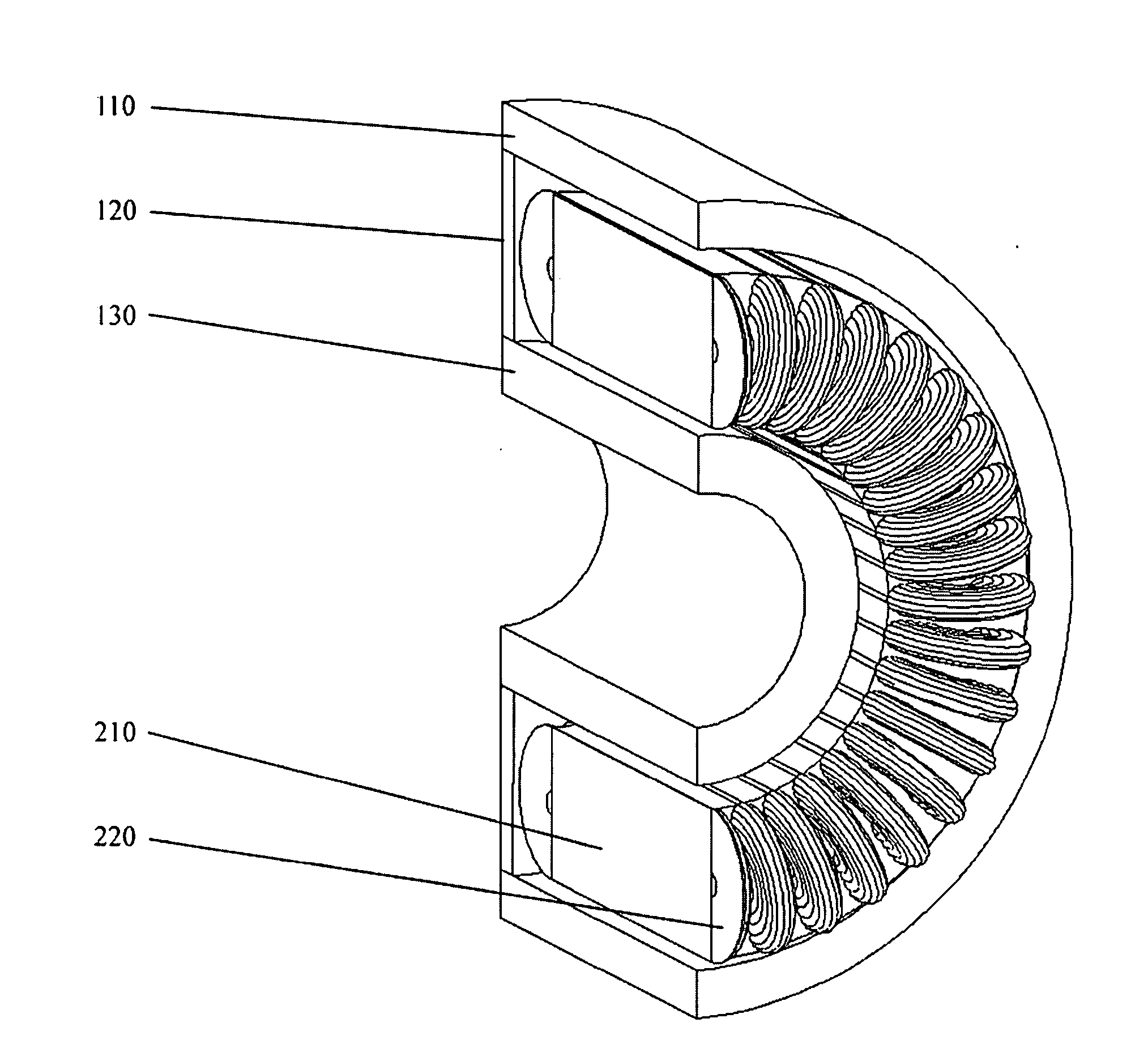
[0060] The following example is for illustration only and is not intended to be limiting. A motor of the present invention with an outer diameter of 1050 mm, inner diameter of 850 mm and a length of 50 mm, could provide a torque of 500 Newton meters, well in excess of that required to start typical gas turbines. The motor could function as a generator, conservatively providing 200 to 400 kW depending upon operating speed. The total active mass of such an electric motor would be less than 100 kg, including approximately 40 kg of mass rotating at turbine speeds. The air-gap of such a motor would be 5 mm, permitting integration with the gas friction and sealing requirements of the gas turbine.


PUM


Abstract

The invention consists of a ring motor, in which a first ring forms a toroidally wound stator and a second ring forms the rotor. A turbine is fixed to the rotor ring. The invention is specifically targeted towards the environment inside a gas turbine, in which hot gases may permeate the space between rotor and stator.

Description

CROSS-REFERENCE TO RELATED APPLICATIONS [0001] This application claims the benefit of U.S. Provisional Patent Application No. 60 / 851,404, filed Oct. 13, 2006. This application is a Continuation-in-Part of U.S. patent application Ser. No. 11 / 900,614, filed Sep. 11, 2007, which claims the benefit of U.S. Provisional Patent Application No. 60 / 843,930, filed Sep. 11, 2006, and is a Continuation-in-Part of U.S. patent application Ser. No. 11 / 517,086, filed Sep. 6, 2006, which claims the benefit of: Provisional Patent Application No. 60 / 714,603, filed Sep. 7, 2005; Provisional Patent Application No. 60 / 737,587, filed Nov. 16, 2005; and International Application No. PCT / US2005 / 045409, filed Dec. 13, 2005. patent application Ser. No. 11 / 900,614 is also a Continuation-in-Part of U.S. patent application Ser. No. 11 / 792,967, filed Jun. 13, 2007, which is the U.S. National Stage Application of International Application No. PCT / US2005 / 045409, filed Dec. 13, 2005, which International Application ...

Claims


Application Information

Patent Timeline
Patent Type & Authority Applications(United States)
IPC IPC(8): H02K19/00H02K3/00H02K1/00
CPCF02C7/268H02K3/28H02K7/1823H02P29/0038H02K17/02H02K17/42H02P9/44H02K11/048H02P29/50H02M7/00
Inventor EDELSON, JONATHAN SIDNEY
Owner BOREALIS TECH LTD
Why Eureka
Try Eureka