Backlight source

a backlight source and backlight technology, applied in the field of backlight sources, can solve the problems of affecting the use efficiency of light and angle of view, lcd cannot provide bright image actively, and lowering image quality, so as to improve the brightness uniformity of backlight sources, reduce overall thickness of backlight modules, and improve the effect of mixing ligh

Active Publication Date: 2008-02-21
AU OPTRONICS CORP
View PDF6 Cites 7 Cited by
  • Summary
  • Abstract
  • Description
  • Claims
  • Application Information

AI Technical Summary

Benefits of technology

[0013]An objective of the present invention is to provide a backlight source. The backlight source has at least two substantially different luminescence types of electroluminescence devices and coordinates at least one of the arrangement positions and the arrangement spacing of the electroluminescence devices to improve the brightness uniformity of the backlight source and make the mixed light better. Moreover, the overall thickness of backlight module can be reduced, due to the brightness uniformity promotion.

Problems solved by technology

Because the LCD is a non-self-luminous display device, the LCD cannot provide bright image actively.
Furthermore, the light emitting angle of the backlight module affects the usage efficiency of light and the angle of view directly.
The dark band phenomenon lowers the quality of the image.

Method used


Image

  • Backlight source
  • Backlight source
  • Backlight source

Examples


Embodiment Construction

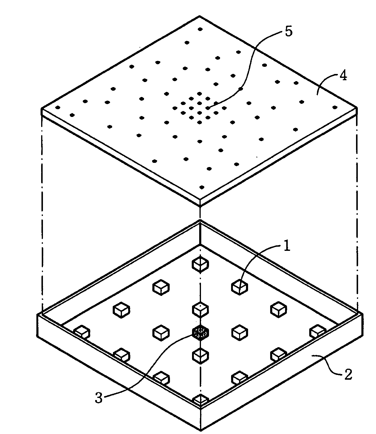
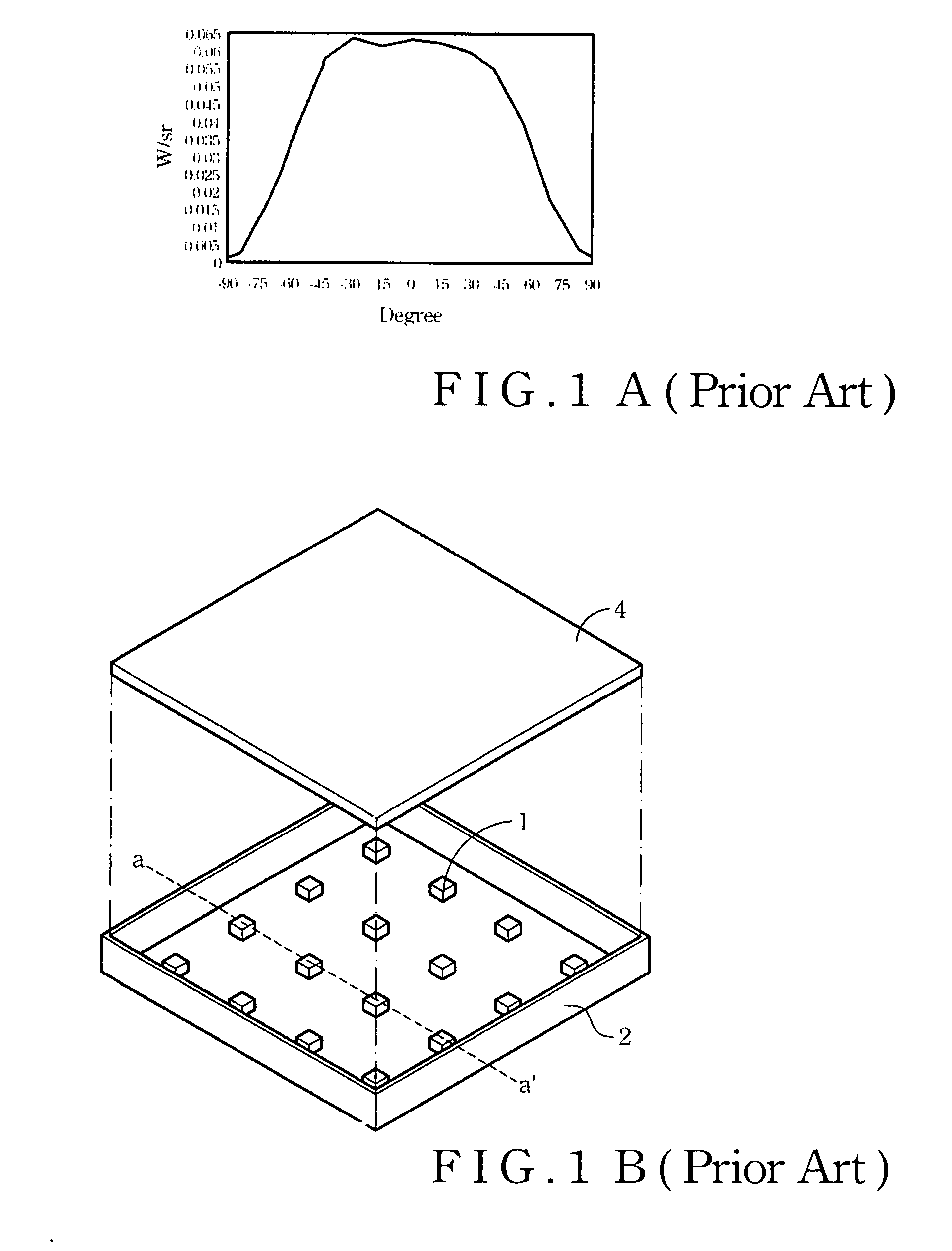
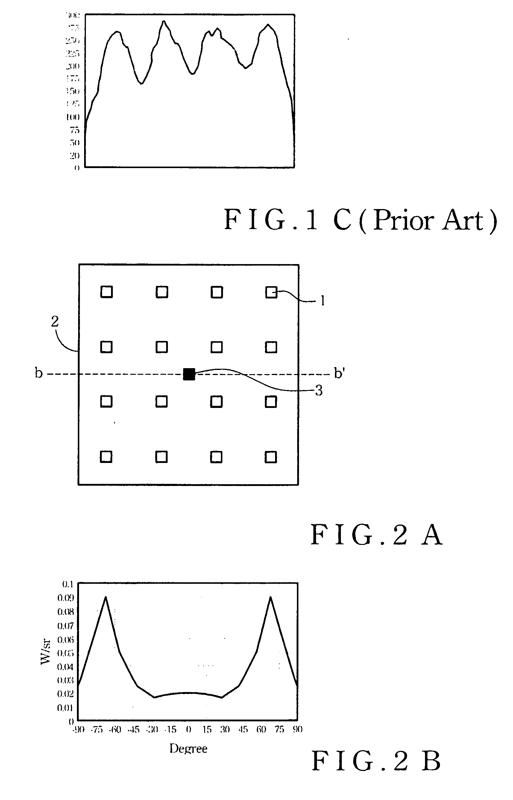
[0035]Referring to FIG. 2A, which illustrates a top-view of a backlight source according to the present invention. The backlight source of the present invention comprises at least one first electroluminescence device (ELD) 3 and a plurality of second electroluminescence devices 1. The first electroluminescence device 3 and the second electroluminescence devices 1 are all disposed inside the backlight source casing 2.

[0036]Wherein, the first electroluminescence device 3 generates light with a first luminescence type. Referring to FIG. 2B, which illustrates the optical field distribution of the first luminescence type of the single first electroluminescence device 3. The first luminescence type comprises a side light type, and the maximum luminous intensity of the first electroluminescence device 3 is located at an absolute value of about 70 degrees. In other words, the maximum luminous intensity of the first electroluminescence device 3 is located at plus or minus about 70 degrees.

[0...


PUM


Abstract

A backlight source has different luminescence types of electroluminescence devices and coordinates at least one of the arrangement positions and the arrangement spacing of the electroluminescence devices to improve the brightness uniformity of the backlight source and make the mixed light better. Moreover, because of the brightness uniformity promotion, the overall thickness of backlight module can be reduced.

Description

BACKGROUND OF THE PRESENT INVENTION[0001](1) Field of the Present Invention[0002]The present invention relates to a backlight source and, more particularly, to a backlight source with at least two kinds of electroluminescence devices.[0003](2) Description of the Prior Art[0004]Following the advancement of the display technique, the liquid crystal display (LCD) is widely applied to substitute for traditional CRT monitor. The LCD is very popular by the consumer, since its light weight, small volume, and low-radiation. The LCD has been regarded as the mainstream product at present, and widely applied to many electronic products, such as computer, personal digital assistant (PDA), laptop, digital camera, and mobile phone.[0005]Because the LCD is a non-self-luminous display device, the LCD cannot provide bright image actively. Thus, the LCD needs a backlight module to provide illumination of the image. Generally speaking, the luminous character of the backlight source is highly bright an...

Claims


Application Information

Patent Timeline
Patent Type & Authority Applications(United States)
IPC IPC(8): H01J1/62
CPCG02F1/133603H01J1/63G02F1/133606
Inventor KO, YA-HUACHEN, CHIH-KUANGLIN, HSIN-WU
Owner AU OPTRONICS CORP
Why Eureka
Try Eureka