
Plasma display apparatus and method of driving the same

Inactive Publication Date: 2008-02-21
LG ELECTRONICS INC
View PDF0 Cites 0 Cited by
  • Summary
  • Abstract
  • Description
  • Claims
  • Application Information

AI Technical Summary

Benefits of technology

[0018] Accordingly, this document provides a plasma display apparatus and a method of driving the same capable of simplifying a configuration of a circuit constituting the plasma display apparatus and reducing the fabrication cost thereof.

Problems solved by technology

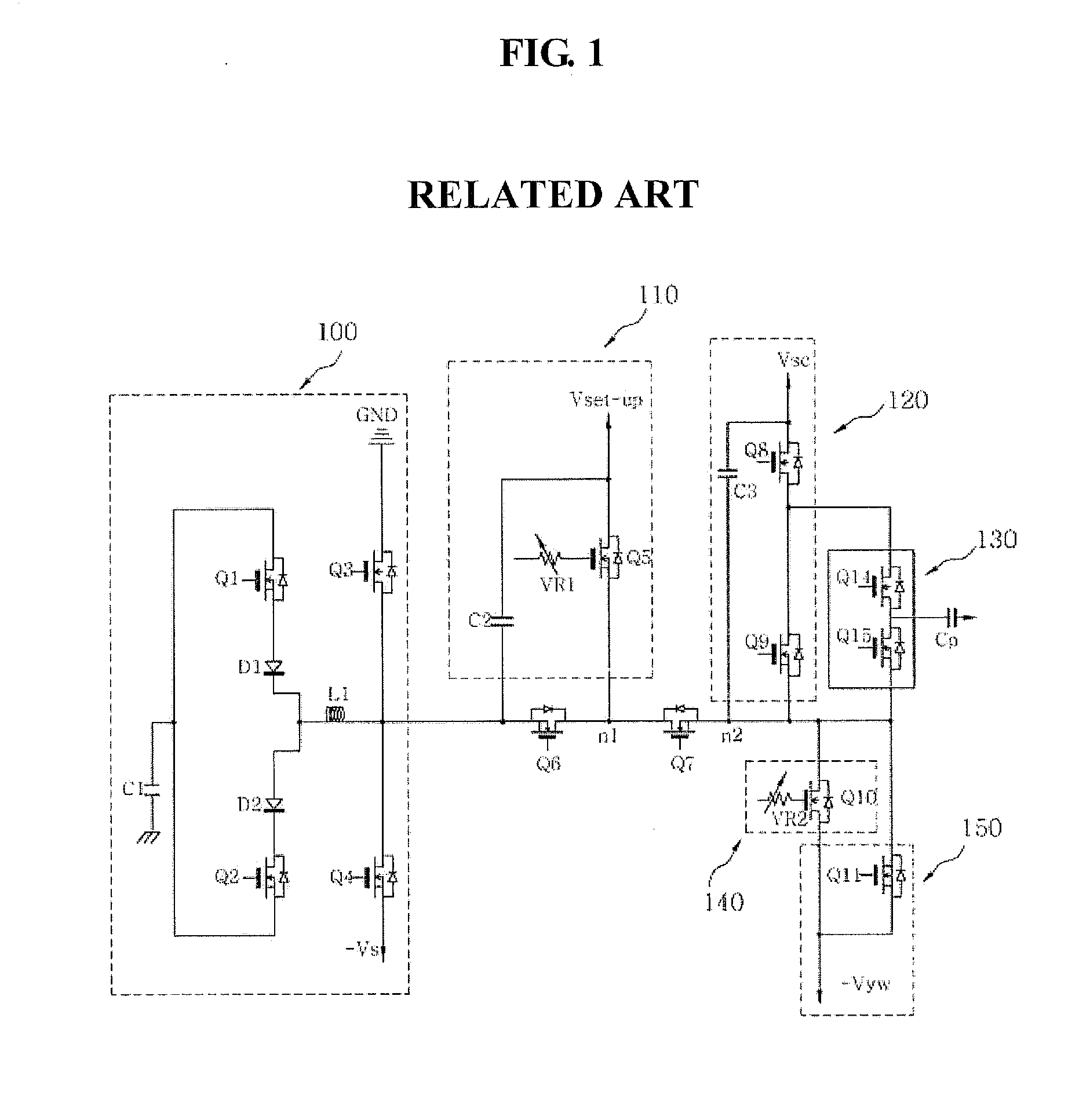
Therefore, it is not easy that the circuit of FIG. 1 drives a plasma display panel having a long-gap structure, in which a distance between a scan electrode requiring a high setup voltage and a sustain electrode is long.
However, in such a case, a separate voltage source for supplying the setup bias voltage is required, thereby causing an increase in the fabrication cost.
Further, the sixth switch Q6 used as a high voltage pass bottom switch is expensive, thereby causing an increase in the fabrication cost.

Method used


Image

  • Plasma display apparatus and method of driving the same
  • Plasma display apparatus and method of driving the same
  • Plasma display apparatus and method of driving the same

Examples


Embodiment Construction

[0047] Reference will now be made in detail embodiments of the invention examples of which are illustrated in the accompanying drawings.

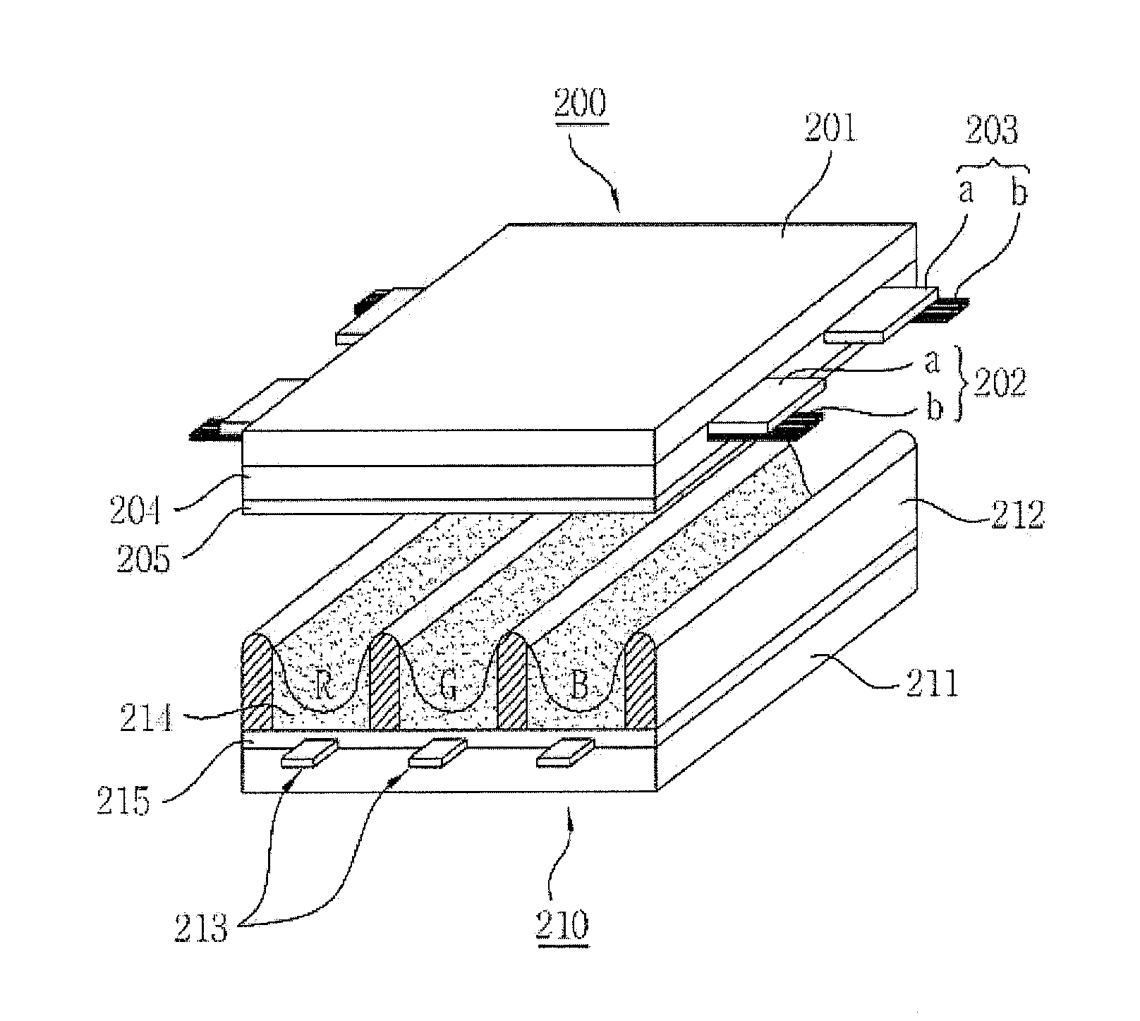
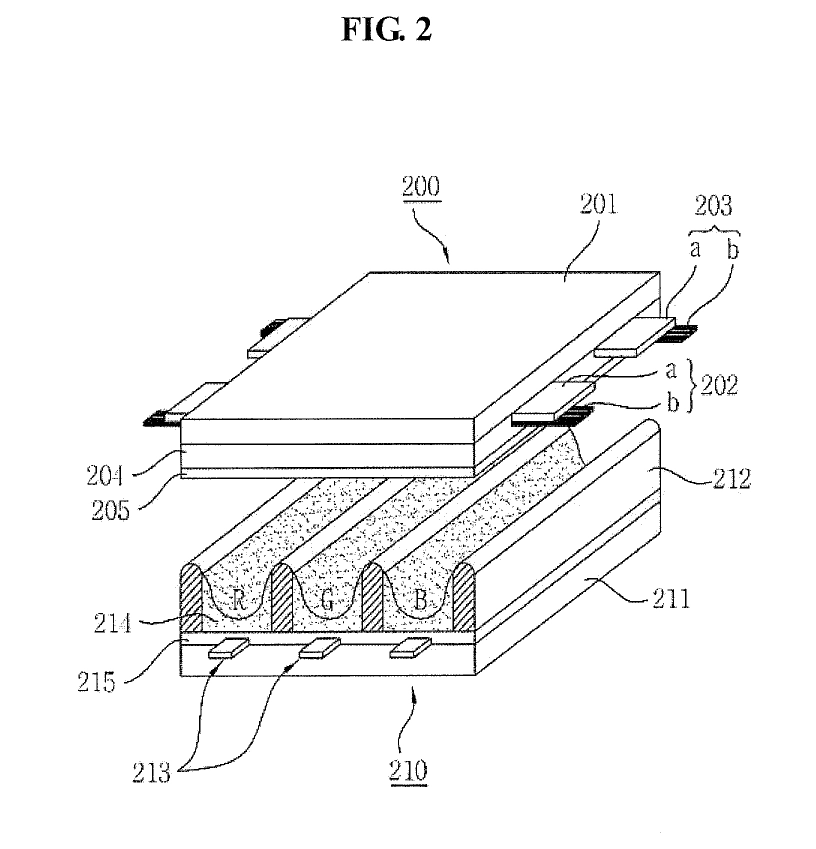
[0048]FIG. 2 illustrates the structure of a plasma display panel of a plasma display apparatus according to an exemplary embodiment.

[0049] As illustrated in FIG. 2, a plasma display panel of a plasma display apparatus according to an exemplary embodiment includes a front panel 200 and a rear panel 210 which are coupled in parallel to oppose to each other at a given distance therebetween. The front panel 200 includes a front substrate 201 being a display surface on which an image is displayed. The rear panel 210 includes a rear substrate 211 constituting a rear surface. A plurality of scan electrodes 202 and a plurality of sustain electrodes 203 are formed in pairs on the front substrate 201. A plurality of address electrodes 213 are arranged on the rear substrate 211 to intersect the scan electrodes 202 and the sustain electrodes 203.

[0050] The s...


PUM


Abstract

A plasma display apparatus and a method of driving the same are disclosed. The plasma display apparatus includes a drive integrated circuit (IC) supplying a driving voltage to a scan electrode, a scan reference voltage supply unit, a setup supply unit, and a sustain pulse supply unit. The scan reference voltage supply unit supplies a first voltage to the drive IC during a reset period, and supplies a scan reference voltage to the drive IC during an address period. The setup supply unit supplies a pulse gradually rising from the first voltage to a second voltage to the drive IC during the reset period. The sustain pulse supply unit supplies a sustain pulse having a negative sustain voltage to the drive IC during a sustain period.

Description

[0001] This application claims the benefit of Korean Patent Application No. 10-2006-0078414 filed in Korea on Aug. 18, 2006, which is hereby incorporated by reference. BACKGROUND OF THE DISCLOSURE [0002] 1. Field of the Disclosure [0003] This document relates to a display apparatus, and more particularly, to a plasma display apparatus and a method of driving the same. [0004] 2. Description of the Background Art [0005] Out of display apparatuses, a plasma display apparatus includes a plasma display panel and a driver for driving the plasma display panel. [0006] The plasma display panel has the structure in which barrier ribs formed between a front panel and a rear panel forms unit discharge cell or discharge cells. Each discharge cell is filled with an inert gas containing a main discharge gas such as neon (Ne), helium (He) or a mixture of Ne and He, and a small amount of xenon (Xe). [0007] The plurality of discharge cells form one pixel. For example, a red (R) discharge cell, a gree...

Claims


Application Information

Patent Timeline
IPC IPC(8): G09G3/28
CPCG09G3/2927G09G3/294G09G2300/0426G09G3/298G09G2300/0408G09G3/2965G09G3/296
Inventor PAIK, DONGKILIM, JONGRAEKIM, TAEHEONKIM, WOOTAECHOI, SUNGCHUN
Owner LG ELECTRONICS INC
Learn More