

Optical tomography system
a tomography system and optical technology, applied in the field of optical tomography systems, can solve problems such as interference with reference light beams, and achieve the effect of favorable image quality and stable tomographic images
- Summary
- Abstract
- Description
- Claims
- Application Information
AI Technical Summary
Benefits of technology
Problems solved by technology
Method used
Image

Examples
first embodiment
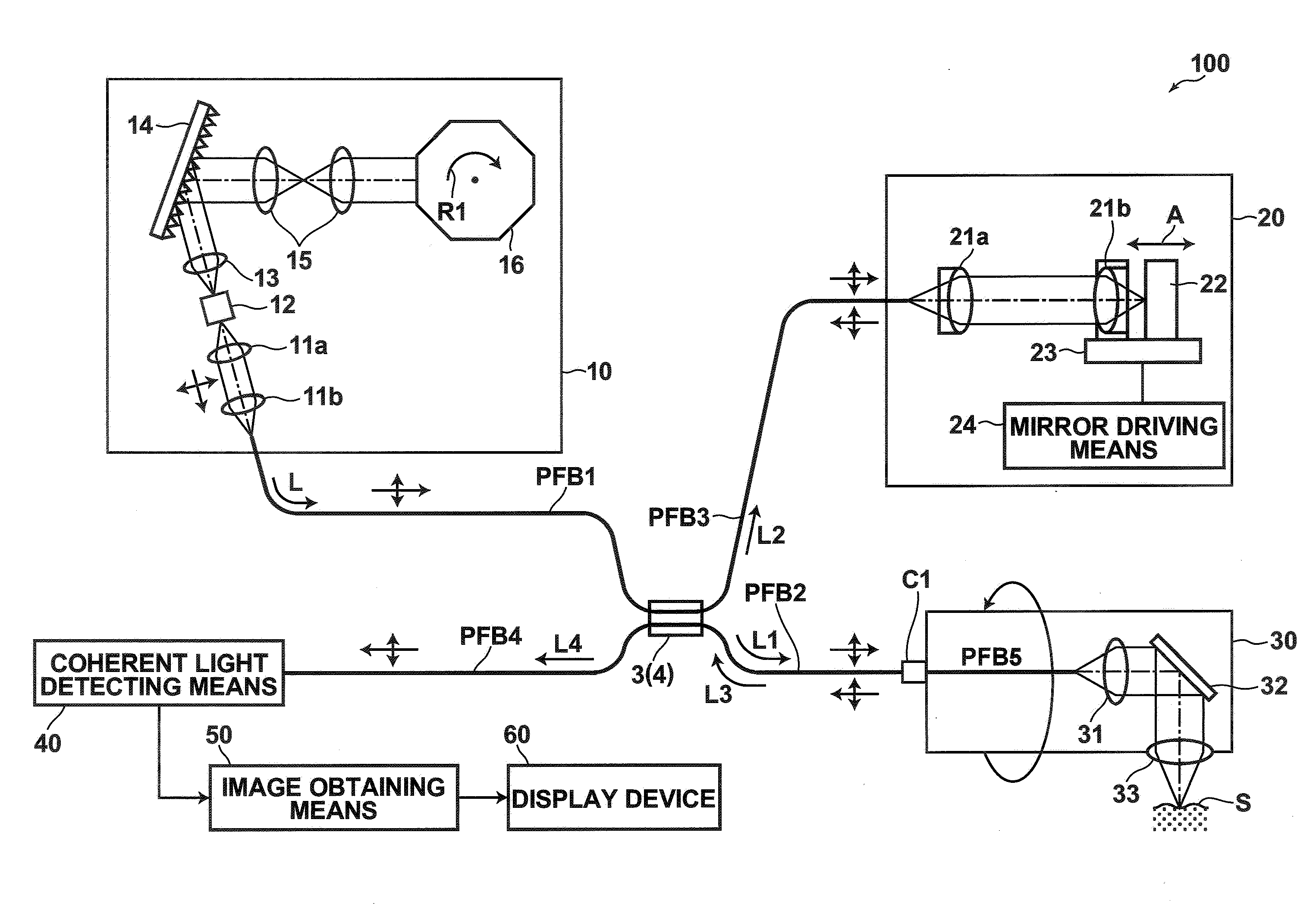
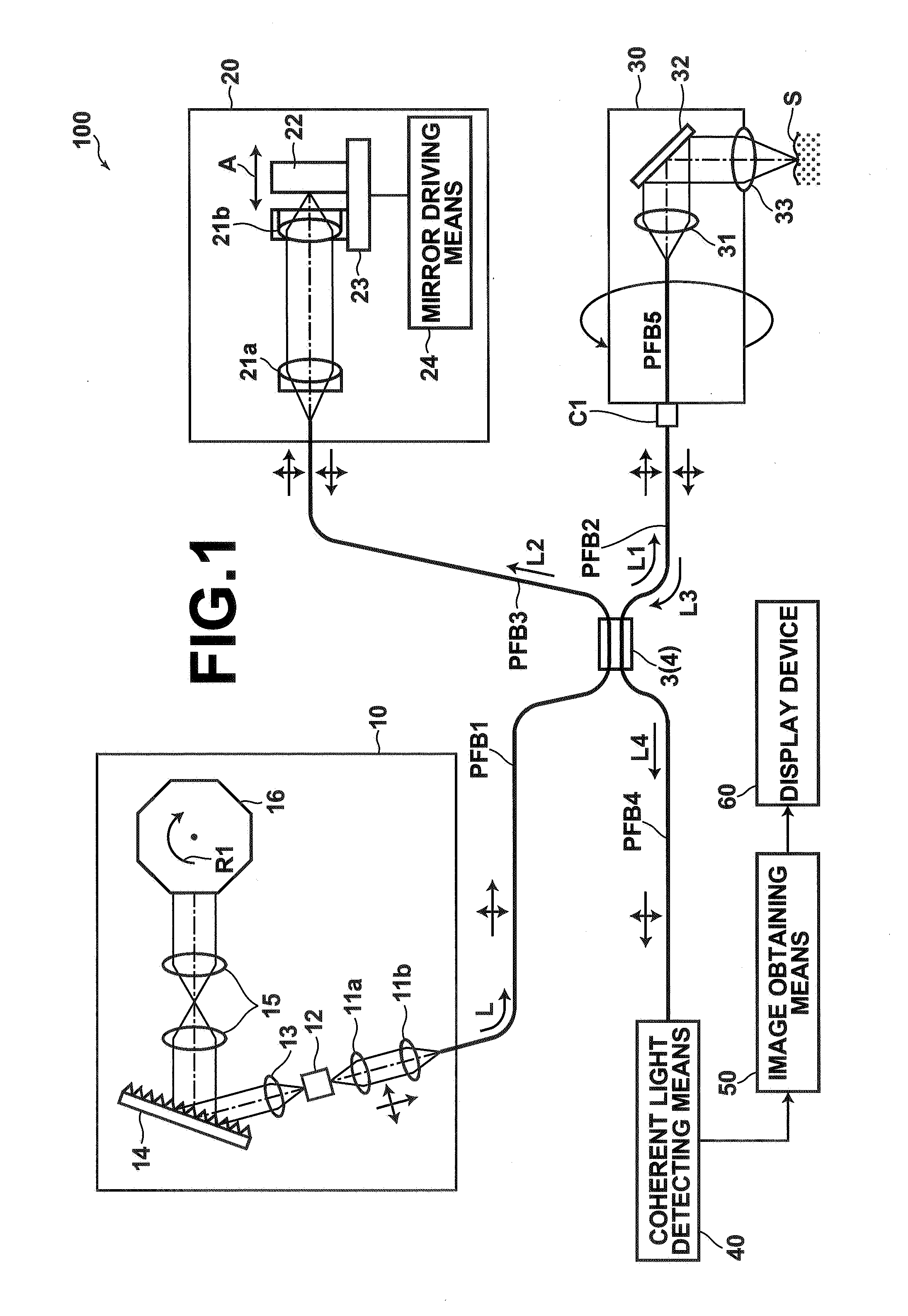
[0082]FIG. 1 is a diagram that illustrates the construction of an optical tomography system 100 according to the present invention. The optical tomography system 100 obtains tomographic images of measurement targets, such as living tissue and cells within body cavities, by SS-OCT measurement. The optical tomography system 100 comprises: a light source unit 10, for emitting a light beam L; a light dividing means 3, for dividing the light beam L emitted from the light source unit 10 into a measuring light beam L1 and a reference light beam L2; an optical path length adjusting means 20, for adjusting the optical path length of the reference light beam L2 output by the light dividing means 3; a probe 30, for guiding the measuring light beam L1 output by the light dividing means 3 to a measurement target S, and for guiding a reflected light beam L3, which is the measuring light beam L1 reflected by the measurement target S; a combining means 4, for combining the reflected light beam L3 a...
seventh embodiment
[0147]Next, an optical tomography system 700 according to the present invention will be described with reference to FIG. 13. The optical tomography system 700 employs the same bulk optical systems as those of the optical tomography system 500 of FIG. 10, to realize the functions of the optical tomography system 600 of FIG. 11. Components of the optical tomography system 700 illustrated in FIG. 13 which are the same as those of the optical tomography system 500 illustrated in FIG. 10 and the optical tomography system 600 of FIG. 11 are denoted with the same reference numerals, and detailed descriptions thereof will be omitted.
[0148]Specifically, the optical tomography system 700 is of a similar structure as the optical tomography system 500, except that: a ½ wavelength plate 701 is added between the light dividing means 502 and the mirror 503; and a interference light detecting means 740 is employed instead of the interference light detecting means 40. The interference light detectin...
ninth embodiment
[0169]The light source unit 610 described above may be applied to other optical tomographs, as long as they are SS-OCT apparatuses. An optical tomography system 706 according to the present invention will be described with reference to FIG. 16, as an example of another optical tomography system that employs the light source unit 610. In the optical tomography system 706, optical paths outside the light source unit are constituted by bulk optical systems. The basic structure of the optical tomography system 706 is the same as that of the optical tomography system 700 illustrated in FIG. 13, except for the above point and that the light source unit 610 is employed instead of the light source unit 510. The structure of the optical tomography system 706 is illustrated in FIG. 16. In FIG. 19, Components which are the same as those of the previous embodiments are denoted with the same reference numerals, and detailed descriptions thereof will be omitted.
[0170]In the optical tomography sys...
PUM
 Abstract
Description
Claims
Application Information