Automatic spotter with electronic control system for pile driving and continuous flight auger drilling leads

a technology of automatic spotter and electronic control system, which is applied in the direction of drilling machines and methods, bulkheads/piles, constructions, etc., can solve the problems of catastrophic failure, affecting the operation of cranes, and requiring considerable skill of crane operators, so as to limit the maximum amount of twist and/or side loading

Active Publication Date: 2008-02-21
DEEP FOUND CONTRACTORS
View PDF14 Cites 17 Cited by
  • Summary
  • Abstract
  • Description
  • Claims
  • Application Information

AI Technical Summary

Benefits of technology

[0011]The present invention relates to a three-axis (x, y and z) pivoting boom box with or without progressive rate rubber springs and at least one electrical feedback sensor attaching the lead to the top of the crane's lattice boom, for use in limiting the maximum amount of twist and/or side loading transmitted into the crane's lattice boom.

Problems solved by technology

The crane's operator requires considerable skill if major equipment damage is to be prevented when pile driving at acute angles.
Incorrect operation can cause catastrophic failure through twisting and/or side loading of the crane's lattice boom if the spotter is not operated in the correct manner.
This system can, over time, get out of phase (due to hydraulic oil leaking past the cylinder's packing and valves) and is unable to self-compensate.
The following problems have, until now, caused considerable damage to the c

Method used


Image

  • Automatic spotter with electronic control system for pile driving and continuous flight auger drilling leads
  • Automatic spotter with electronic control system for pile driving and continuous flight auger drilling leads
  • Automatic spotter with electronic control system for pile driving and continuous flight auger drilling leads

Examples


Embodiment Construction

[0039]Set forth below is a description of what are believed to be the preferred embodiments and / or best examples of the invention claimed. Future and present alternatives and modifications to the preferred embodiments are contemplated. Any alternatives or modifications which make insubstantial changes in function, in purpose, in structure, or in result are intended to be covered by the claims of this patent.

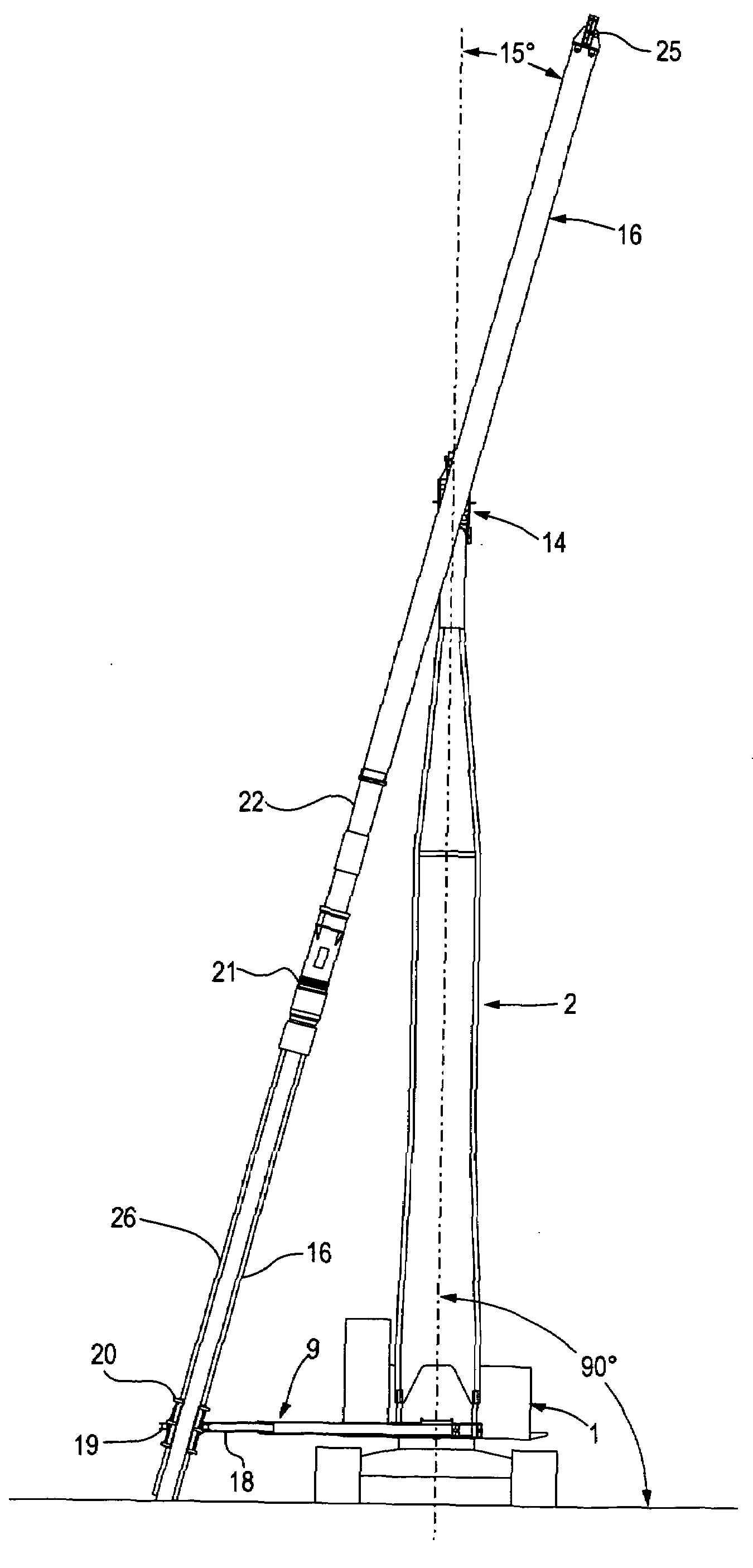
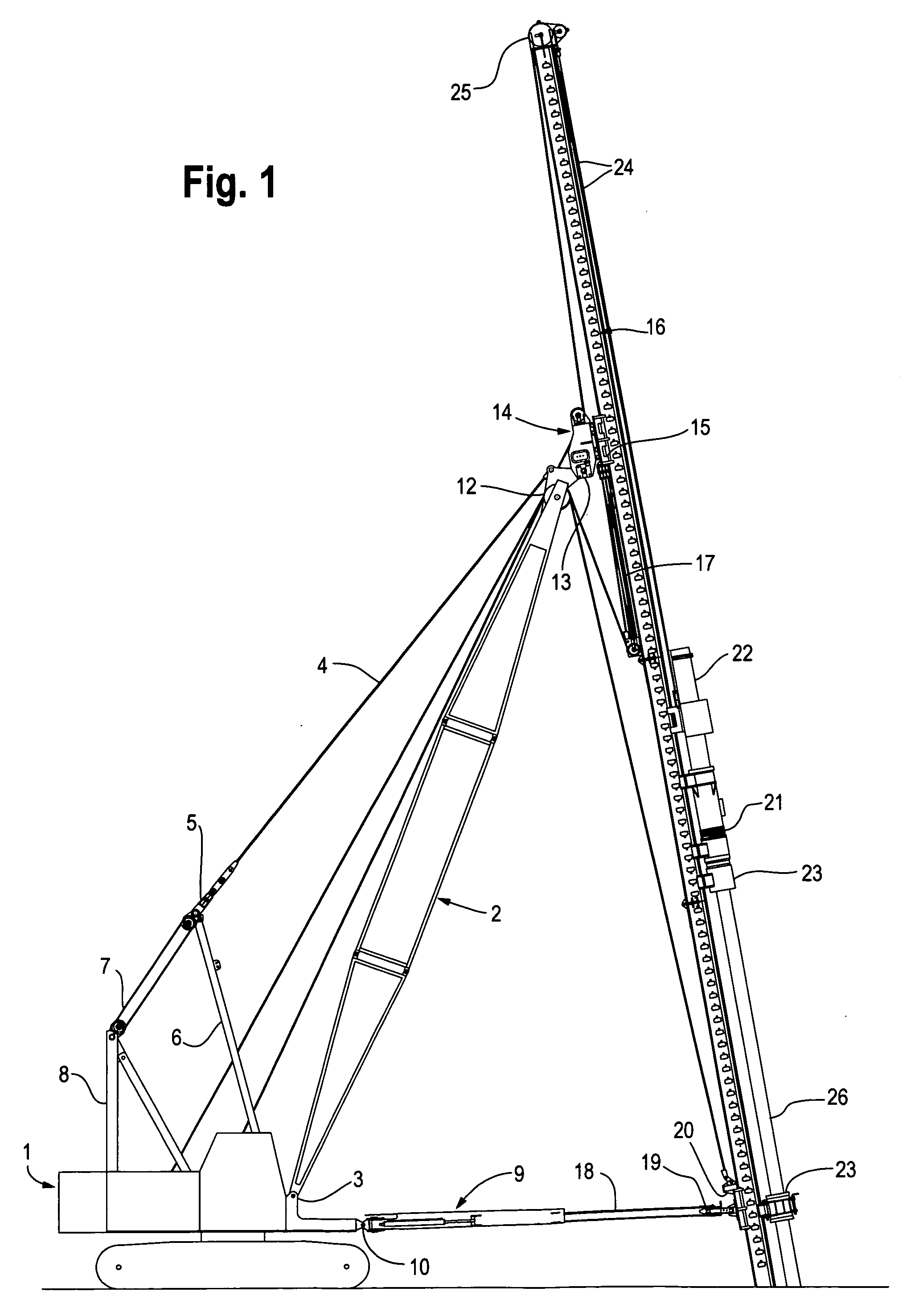
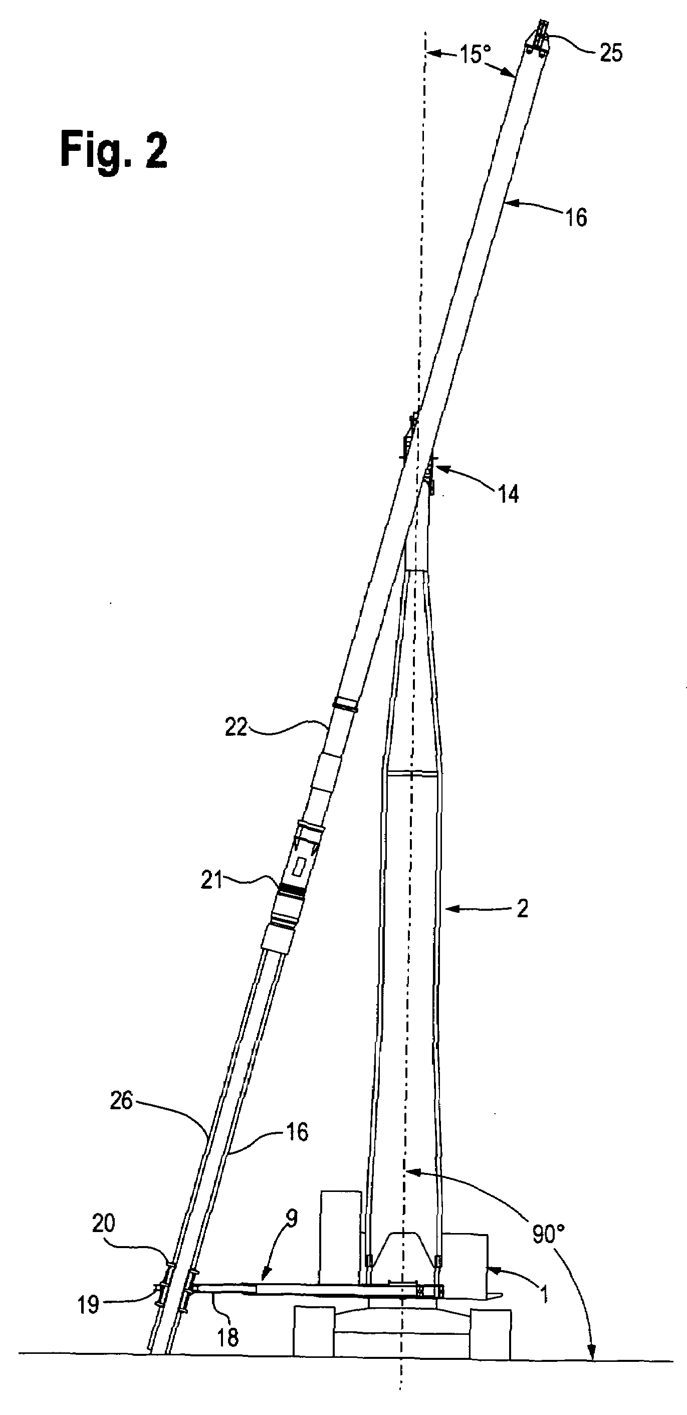
[0040]Referring first to the preferred embodiment of the invention shown in FIG. 1, a detailed description of this example follows, it being recognized that various other examples may be provided that are within the principles of the invention and intended to be covered by the claims. In the preferred example, lattice boom 2 may be attached to the mobile crane's revolving upper frame or base 1 by two pivot pins 3, which form the bottom boom pivot point, and at the top by pendent cables 4, spreader bar 5, live mast 6, multi-part cable 7 and gantry 8. Cable 7 may be spooled in and ...


PUM


Abstract

A lifting device such as a mobile crane having a main body and a boom, such as a lattice boom, for supporting a pile lead for, e.g., pile driving or continuous flight auger drilling, and a method of using same. A hydraulically operated mechanical spotter arm may be attached between the device body and the pile lead. Electronic position sensors on the spotter arm may be used to measure angular relationships between the pile lead and the spotter arm. Position sensors on a boom box on the boom may also be used. When the pile lead is swung, information from the sensors may be used by an electronic control system to automatically maintain the pile lead in a desirable position, limiting torque induced in the boom. The boom box position sensors may be used to counter-steer the spotter arm to further limit torque. The boom box may also be fitted with rubber springs to permit controlled pile lead deflection while limiting load transmitted to the boom. Other aspects of the invention will become apparent from the disclosure.

Description

BACKGROUND OF THE INVENTION[0001]The present invention generally relates to improved crane operation. More specifically, the invention relates to an electronic control system that prevents the crane's operator from overstressing the lattice boom when operating the hydraulic spotter and provides continuous, self-compensation against spotter hydraulic system leakage (hydraulic drift) caused by the pile lead being twisted when continuous-flight-auger (CFA) drilling or pile driving.[0002]Pile driving and CFA drilling are well-established methods that have changed very little in basic principle since their introduction many years ago, as described in U.S. Pat. Nos. 3,550,693, 1,888,3217 and 4,102,094, each incorporated by reference herein in its entirety. The crane's operator requires considerable skill if major equipment damage is to be prevented when pile driving at acute angles. This is of particular importance during sideways battered piles. Incorrect operation can cause catastrophic...

Claims


Application Information

Patent Timeline
IPC IPC(8): E21B19/00E02D11/00
CPCE02D11/00E02D7/16
Inventor LLOYD, PETERSTARK, WILLIAM F
Owner DEEP FOUND CONTRACTORS
Why Eureka
Try Eureka