
Wireless communications system and method

a wireless communication and wireless technology, applied in the field of wireless communication systems and methods, can solve the problems of inability to connect two specific electronic components at the same time, difficult communication between more than two electronic devices at one time via cabling, and user flexibility in linking more than two electronic devices together for communication, etc., to achieve negligible power consumption and high security.

Inactive Publication Date: 2008-02-21
VISTEON GLOBAL TECH INC
View PDF98 Cites 81 Cited by
  • Summary
  • Abstract
  • Description
  • Claims
  • Application Information

AI Technical Summary

Benefits of technology

Enables automatic, secure, and efficient wireless communication between various electronic devices and vehicle subsystems, enhancing convenience and reducing costs by eliminating the need for cables and manual intervention, while supporting a wide range of applications including vehicle diagnostics and data transfer.

Problems solved by technology

Thus, the same communications cabling needed for connecting two specific electronic components often can only be used to connect those two components, and not to connect different combinations of other electronic components.
Thus, interconnecting different combinations of electronic devices for intercommunication is often possible only with specific and often expensive cabling.
Communication between more than two electronic devices at one time via cabling presents even greater difficulty.
Thus, the user often has very limited flexibility in linking more than two electronic devices together for communication.
In certain environments, such as within an automobile, it is often impractical for the user to manually connect and disconnect cabling between two or more electronic devices, especially when the electronic devices are portable devices which the user desires to carry when leaving the vehicle.
Additionally, it would be extremely impractical to attempt to connect such personal electronic devices to existing subsystems of a vehicle, such as an overhead display console, with physical cables that would be loose within the vehicle.
Such cabling could easily interfere with the driver's convenient operation of the various controls of the vehicle or with the comfort and convenience of other passengers in the vehicle.
However, previously developed implementations of these methods of information transfer have suffered from significant drawbacks.
Such a line of sight is often not practical and / or difficult to maintain in certain operating environments, such as while traveling in an automobile.
Radio frequency data communication has traditionally been hampered by the lack of a standard communications protocol for data transfer which permits data to be transmitted between two or more independent electronic devices.
A further limitation with RF data transfer systems has been the lack of a low cost, low power RF transceiver able to be inexpensively integrated with compact, portable electronic devices such as notebook computers, cellular telephones, hand-held PDAs, pagers, etc., to enable convenient RF information transfer between two or more of such devices over short distances of up to, for example, about ten meters.
Still another limitation with traditional methods for transmitting data between electronic devices has been the lack of an “automatic” or “unconscious” connection when the devices are in proximity with one another.
This limitation has up until the present required the user to provide one or more commands to at least one of the electronic devices to begin the process of transferring data between the two devices.

Method used


Image

  • Wireless communications system and method
  • Wireless communications system and method
  • Wireless communications system and method

Examples


Embodiment Construction

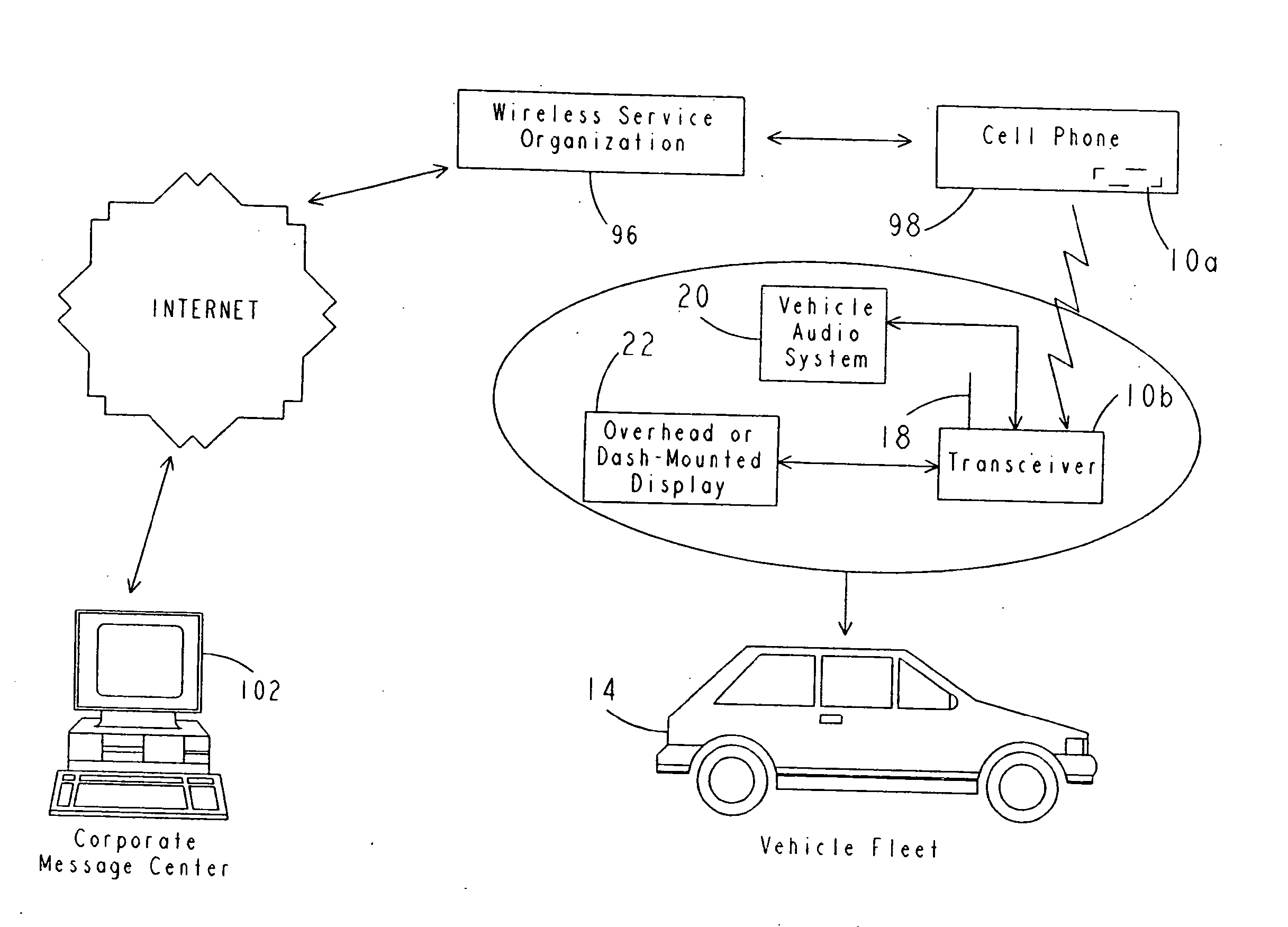
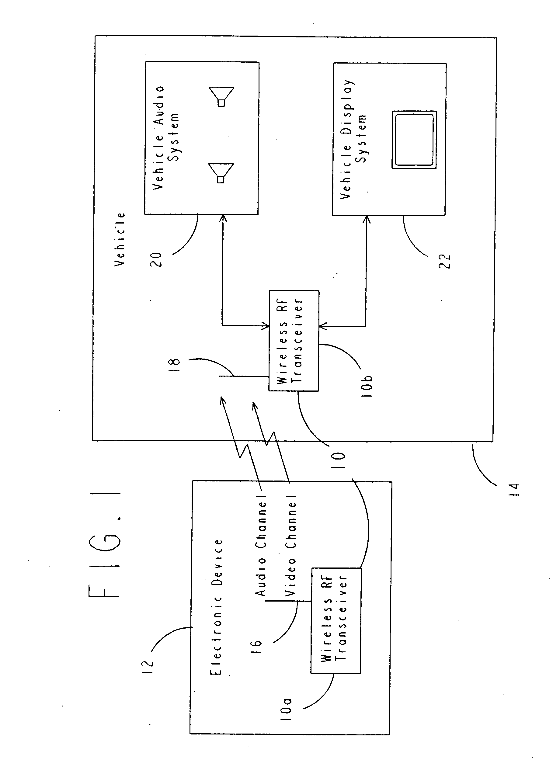
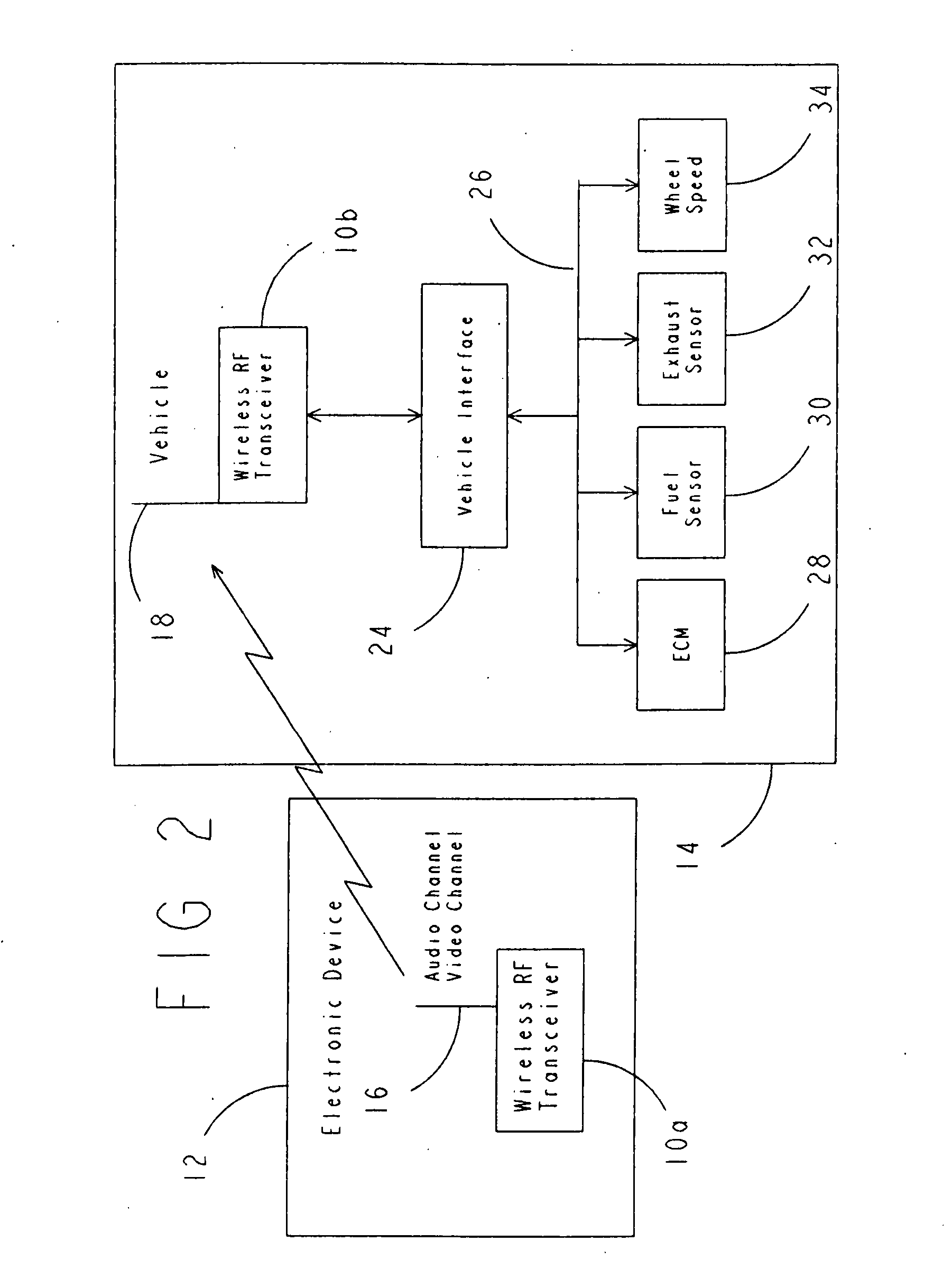
[0035] Referring to FIG. 1, a wireless communications system 10 in accordance with a preferred embodiment of the present invention is illustrated. The present invention is broadly directed to a wireless communications system 10 in which at least one pair of RF transceivers 10a and 10b are used to create a wireless communications link between at least two independent electronic devices. Each RF transceiver 10a and 10b operates in accordance with a suitable wireless communications protocol or standard to enable wireless communications between the transceivers 10a and 10b. The specific protocol or standard used also preferably enables the wireless communications link to be established automatically when the two RF transceivers come into proximity with each other. The specific protocol or standard may be the Bluetooth communications standard or the Shared Wireless Access Protocol-Cordless Access (SWAP-CA) specification, or any other suitable wireless communications specification that en...


PUM


Abstract

A system for communicating information facilitates wireless communication between electronic devices. The system includes a transceiver provided in a vehicle. The transceiver communicates with an electronic device located external to the transceiver using a Bluetooth communications standard.

Description

CROSS REFERENCE TO RELATED APPLICATIONS [0001] This application is a Continuation of U.S. application Ser. No. 09 / 979,199 (National Stage of PCT / US2000 / 014692), filed May, 26, 2000, incorporated herein by reference in its entirety, which claims priority from Provisional Application U.S. application Ser. No. 60 / 135,979, filed May 26, 1999, incorporated herein by reference in its entirety.BACKGROUND OF THE INVENTION [0002] This invention relates to wireless communications devices, and more particularly to a wireless communications system and method which facilitates an automatic wireless connection and wireless communication of voice and / or data information between various electronic components such as notebook computers, cellular telephones, hand held computing devices, pagers, audio devices, display terminals and other electronic systems. [0003] With the dramatically increasing popularity of various personal electronic information and computing devices, there has been an increasing ...

Claims


Application Information

Patent Timeline
Patent Type & Authority Applications(United States)
IPC IPC(8): H04M1/00G07C5/00H04B7/26H04L12/56H04L29/06H04L29/08H04M1/60H04W4/44H04W4/48H04W4/80
CPCG07C5/008G06K7/10386H04L29/06H04M1/6041H04M1/6091H04M2250/02H04W4/04H04W84/18H04W88/04H04W88/06H04L67/14H04L67/12H04L69/329H04W4/008H04B7/2609H04W4/80H04B7/26H04W4/48H04W4/44H04L9/40H04B1/3822
Inventor WITKOWSKI, TODD R.DYKEMA, KURT A.GEERLINGS, STEVEN L.ZEINSTRA, MARK L.
Owner VISTEON GLOBAL TECH INC
Learn More