Variable shaft flexibility in endoscope

a flexible, endoscope technology, applied in the field of endoscopes, can solve the problems of limited flexibility and control of known endoscopes, high undesirable interference with internal organs, and difficultness, and achieve the effect of reducing its “flexibility

Inactive Publication Date: 2008-02-21
KARL STORZ ENDOVISION INC
View PDF20 Cites 3 Cited by
  • Summary
  • Abstract
  • Description
  • Claims
  • Application Information

AI Technical Summary

Benefits of technology

[0012]In one embodiment, the endoscope uses a fibrous ionic polymeric material or similar material which changes in physical characteristics (such as length and rigidity) in response to an applied electrical current to achieve variable shaft rigidity, which is controllable by the operator. The endoscope is further provided as a conventional endoscope that may be deflected by mechanical means, providing the operator with total control of the endoscope.
[0014]The relatively thin layers of polymeric material may further be applied as, for example, a tube integral with and around the shaft of the endoscope in one or more sections. It is contemplated that the layer(s) of polymeric material may be constrained at one or more points to the shaft. In this manner, the application of a stimulus, such as, for example, an electrical current, will cause the polymeric material to contract over the flexible shaft section. Depending on the fixture, this will act to temporarily “stiffen” the section and reduce its “flexibility.” When this current is removed, however, the material relaxes restoring the original flexibility to the endoscope so that the operator can use the flexible endoscope in a conventional fashion.

Problems solved by technology

One challenge faced with the use of endoscopes is positioning the endoscope into a tight or difficult to access areas within a body cavity.
It is understood that it is highly undesirable to impinge upon the internal organ with the endoscope so as not to damage the surrounding tissue.
This can become especially challenging when the endoscope must be deflected at a severe angle.
However, the flexibility and control of known endoscopes is limited.
A number of systems have, with limited success, sought to provide a flexible endoscope shaft having increased control.
Upon application of an electrical current, the diameter of the tunnels contracts such that the wires come into contact with the inside of the tunnel surface causing the overtube to become rigid because the wire is not allowed to slip longitudinally with respect to the tunnel.
While this provides some increased control, this device is separate from the scope that is used, which increases the size and the diameter of the device to be inserted into the cavity.
For precise endoscopic procedures, this is unacceptable.
Further, Ewers et al. does not allow for a contraction or expansion of the length of the endoscope shaft and, in fact, states that this feature is undesirable.
In addition, Ewers et al. does not provide for specific control of one or more area of the shaft where the length of the shaft in a particular area may be altered or made more rigid.
However, Banik et al. is disadvantageously provided as a disposable or a single use device.
This disadvantageously means that the endoscope can not also be utilized as a standard mechanically flexible endoscope.
In addition, Banik et al. due to among other things “single use economics”, uses “wireless interface chipsets” rather than “electrical connections.” However, power signals cannot be sent in a wireless format, and therefore, Banik et al. has resorted to providing a portable power source for providing power to the actuators.
While having a relatively short-term use battery for a disposable system is feasible, providing a battery to power a non-disposable endoscope is highly undesirable as such a power source would dramatically increase the size and the weight of the device.

Method used


Image

  • Variable shaft flexibility in endoscope
  • Variable shaft flexibility in endoscope
  • Variable shaft flexibility in endoscope

Examples


Embodiment Construction

[0024]Referring now to the drawings, wherein like reference numerals designate corresponding structure throughout the views.

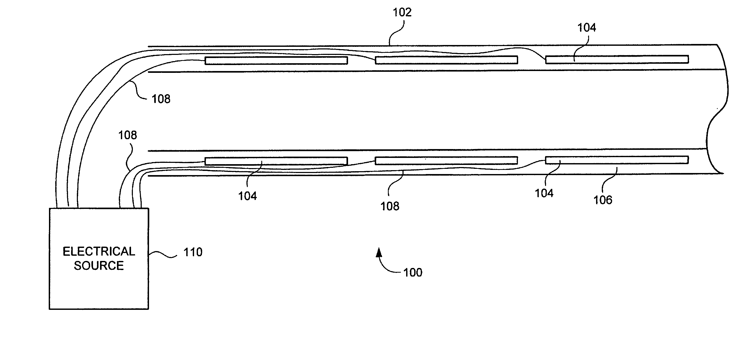
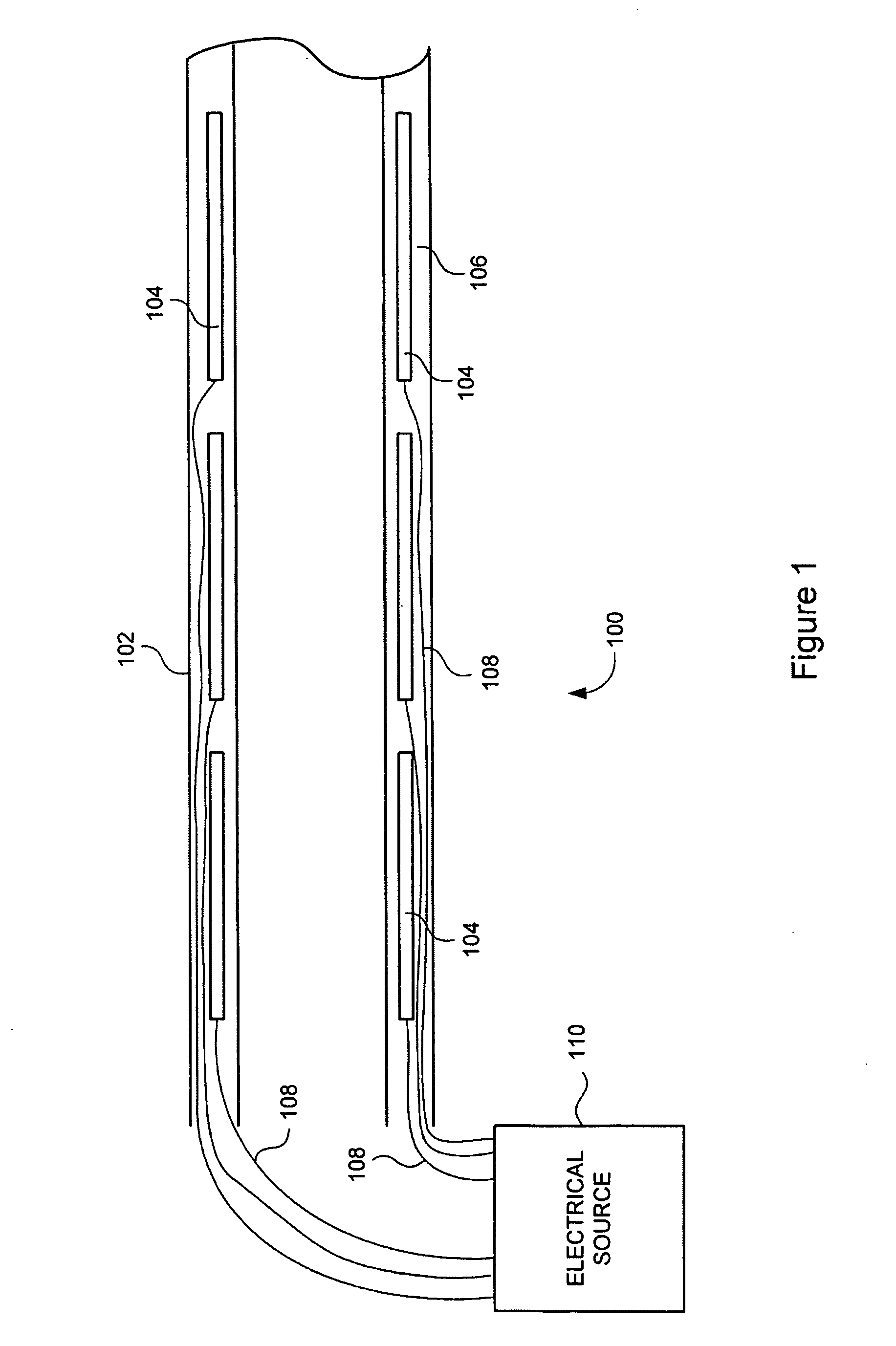
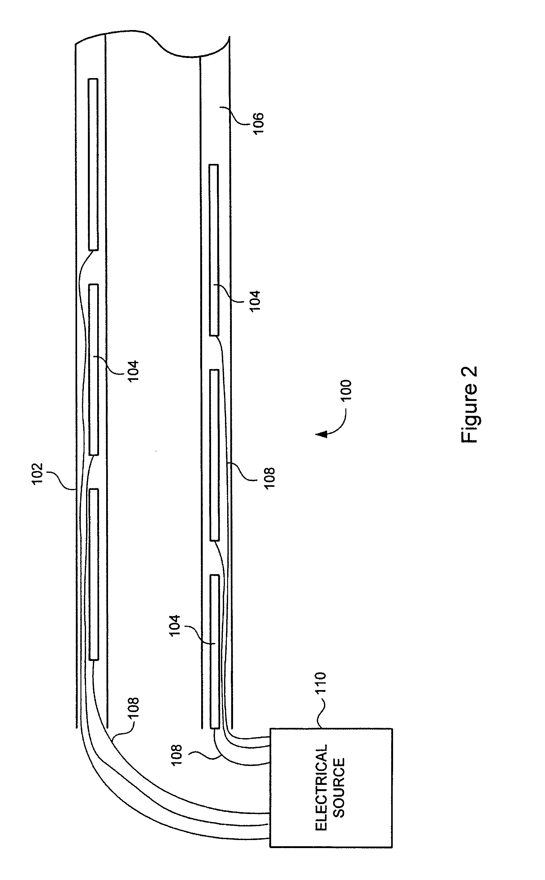
[0025]FIG. 1 is an illustration of a portion of a shaft 102 of flexible endoscope 100. The shaft 102 is shown as a sectional view including elongated segments 104, which are positioned within an outer layer 106 of the shaft 102.

[0026]Also illustrated in FIG. 1 are electrical conductors 108, which are individually electrically connected to the various elongated segments 104. The electrical conductors 108 generally extend from their respective elongated segment 104, through the outer layer 106 and are electrically coupled to an electrical source 110.

[0027]The elongated segments 104 are provided as, for example, a fibrous ionic polymeric material (or similar material), which changes in physical characteristics (such as length and rigidity) in response to a stimulus. In this case, the stimulus is an applied electrical current. In this manner, the applied electrical...


PUM


Abstract

A flexible endoscope providing increased control to an operator or user, the flexible endoscope utilizing an ionic polymeric material positioned in the shaft of the endoscope, such that, upon application of an electrical current to the ionic polymeric material, the material contracts and becomes relatively rigid. The flexible endoscope may further include mechanical controls for control of the flexible shaft allowing the user to simultaneously actuate both the polymeric material and mechanically deflect the shaft.

Description

FIELD OF THE INVENTION[0001]The invention relates to an endoscope having a flexible shaft member, and more specifically to an endoscope that has a shaft of varying flexibility upon the application of an electrical current to an ionic polymer material positioned in the shaft.BACKGROUND OF THE INVENTION[0002]Endoscopes provide a number of advantages when used in minimally invasive surgical procedures allowing the physician to view the surgical area, whether by direct visualization (e.g. via an eyepiece) or via a video screen that displays image data picked-up by a video endoscope. In any event, it is critical that the physician be provided with a clear and unobstructed view of the area ahead of the endoscope.[0003]One challenge faced with the use of endoscopes is positioning the endoscope into a tight or difficult to access areas within a body cavity. For example, it may be necessary to view an area inside an internal organ, which requires the endoscope to be repeatedly bent or deflec...

Claims


Application Information

Patent Timeline
Patent Type & Authority Applications(United States)
IPC IPC(8): A61B1/00
CPCA61B1/00071A61B1/0052A61M2205/0283A61M25/0054A61B1/00078A61B1/0055
Inventor LANDRY, DANA J.
Owner KARL STORZ ENDOVISION INC
Why Eureka
Try Eureka