Powertrain with torque converter and axially compact seven speed dual clutch transmission

a torque converter and transmission technology, applied in the field of powertrains, can solve the problems of limiting the use of countershaft transmissions in some vehicle designs, the cooling circuit of friction shifting clutches is typically relatively complex, etc., and achieves the effect of simplifying the clutch routing

Inactive Publication Date: 2008-02-28
GM GLOBAL TECH OPERATIONS LLC
View PDF3 Cites 44 Cited by
  • Summary
  • Abstract
  • Description
  • Claims
  • Application Information

AI Technical Summary

Benefits of technology

[0005]Unique packaging of the transmission oil pump allows simplified routing of clutch and lubrication oil and compact piloting of a clutch hub that supports the dual friction shifting clutches. Specifically, the clutch hub is configured with clutch hub passages for routing oil delivered from the transmission oil pump to the first and second friction shifting clutches. Preferably, a stationary clutch hub support member at least partially supports the clutch hub and is configured with clutch hub support member passages that are in fluid communication with the clutch hub passages so that oil may be routed from the transmission oil pump to the friction shifting clutches through the stationary clutch hub support member. The transmission oil pump is preferably radially-inward of and partially surrounded by the stationary clutch hub support member. Preferably, a stator support shaft connects a stator portion of the torque converter with the clutch hub support member. The oil pump is positioned radially-outward of the stator support shaft. Preferably the stator support shaft is configured with stator support shaft passages that are in fluid communication with the oil pump to route oil delivered from the oil pump to the torque converter.

Problems solved by technology

Additionally, cooling circuits for the friction shifting clutches are typically relatively complex due to the heat dissipation requirements of these large clutches.
Finally, because lay shaft or countershaft transmissions typically have many sets of axially-aligned, intermeshing gears, overall axial length of countershaft transmissions may limit there use in some vehicle designs.

Method used


Image

  • Powertrain with torque converter and axially compact seven speed dual clutch transmission
  • Powertrain with torque converter and axially compact seven speed dual clutch transmission
  • Powertrain with torque converter and axially compact seven speed dual clutch transmission

Examples


Embodiment Construction

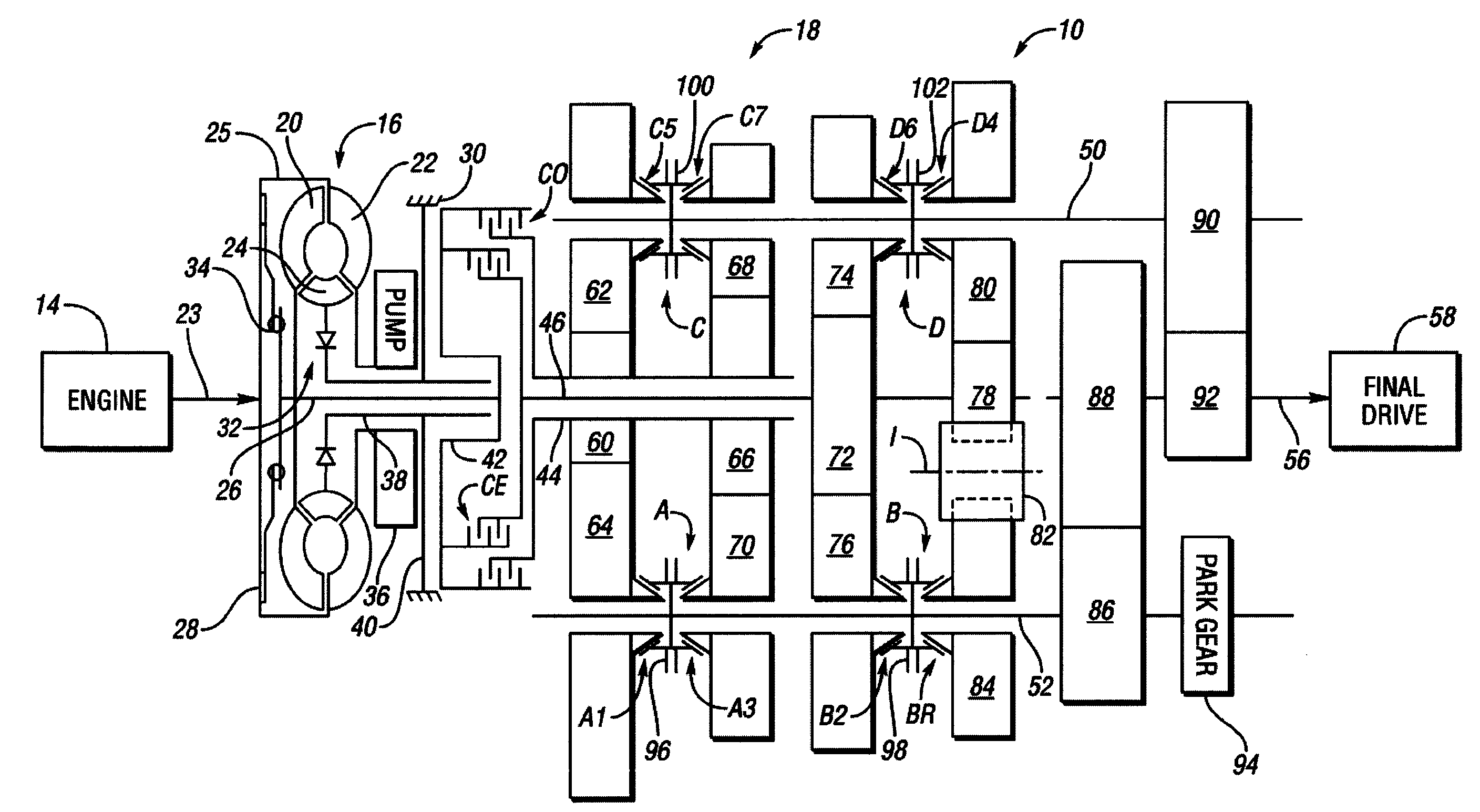
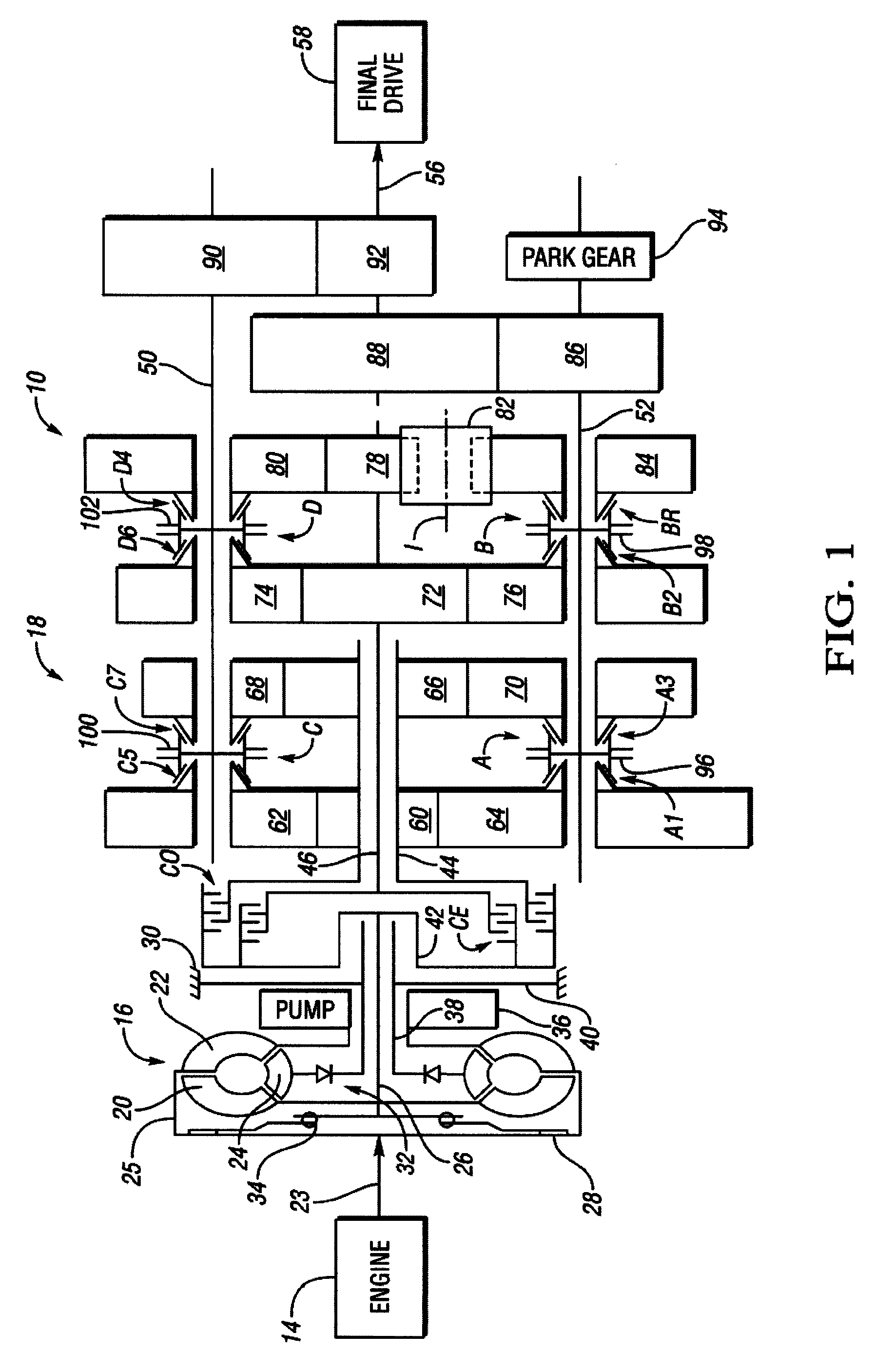
[0010]Referring to the drawings, wherein like reference numbers represent the same or corresponding parts throughout the several views, there is shown in FIG. 1 a powertrain 10 for a vehicle (not shown). The powertrain 10 includes a power source or engine 14, a torque converter 16 and a transmission 18. The torque converter 16 includes a turbine portion 20, a pump portion 22, and a stator portion 24. An engine output shaft 23 is connected for rotation with a hub member 25 that is connected to the pump portion 22. The turbine portion 20 is connected with a transmission input member 26. A fluid coupling between the pump portion 22 and the turbine portion 20 thus operatively connects the engine 14 with the transmission input member 26. The transmission input member 26 is preferably in the nature of a shaft. Selective engagement of a torque converter clutch 28 allows the engine 14 to be directly connected with the input member 26, bypassing the torque converter 16. Preferably, the torqu...


PUM


Abstract

A powertrain having a torque converter, friction input shifting clutches and shared driving gears has an axially compact design, packages a transmission pump between the torque converter and a clutch hub and achieves seven forward speed ratios utilizing four back-to-back synchronizers.

Description

TECHNICAL FIELD[0001]The invention relates to a powertrain having a power source, a torque converter and a compact seven speed transmission with two friction shifting clutches.BACKGROUND OF THE INVENTION[0002]Dual clutch transmissions (DCTs) have been designed with friction launch clutches that connect a vehicle power source such as an engine to a lay shaft transmission. Dual clutch transmissions are known for their sporty, performance-oriented characteristics. Dual clutch transmissions typically exhibit good fuel economy due to good gear mesh efficiency and ratio selection flexibility. Synchronizers are typically used to engage gears with the countershafts to complete power flow from the engaged input clutch to an output shaft. The synchronizers have low spin losses; thus, overall operating efficiency is enhanced. However, dual clutch transmissions have some specific design considerations. For example, due to the high heat that can be generated during slip, the shifting clutches mu...

Claims


Application Information

Patent Timeline
Patent Type & Authority Applications(United States)
IPC IPC(8): F16H3/08
CPCF16H3/006F16H3/097F16H2003/0931Y10T74/19223Y10T74/19288Y10T74/19233F16H2200/0056
Inventor BORGERSON, JAMES B.FITZGERALD, SIMON P.
Owner GM GLOBAL TECH OPERATIONS LLC
Why Eureka
Try Eureka