
Pneumatic paintball gun

a paintball gun and pneumatic technology, applied in the direction of compressed gas guns, white arms/cold weapons, weapons, etc., can solve the problems of reducing the firing or moving distance of paintballs or bullets, not fully using high pressure gas, etc., and achieves the effect of economizing pressurized air and effective use or employing pressurized air or gas

Inactive Publication Date: 2008-02-28
GAN YIAUGUO
View PDF6 Cites 8 Cited by
  • Summary
  • Abstract
  • Description
  • Claims
  • Application Information

AI Technical Summary

Benefits of technology

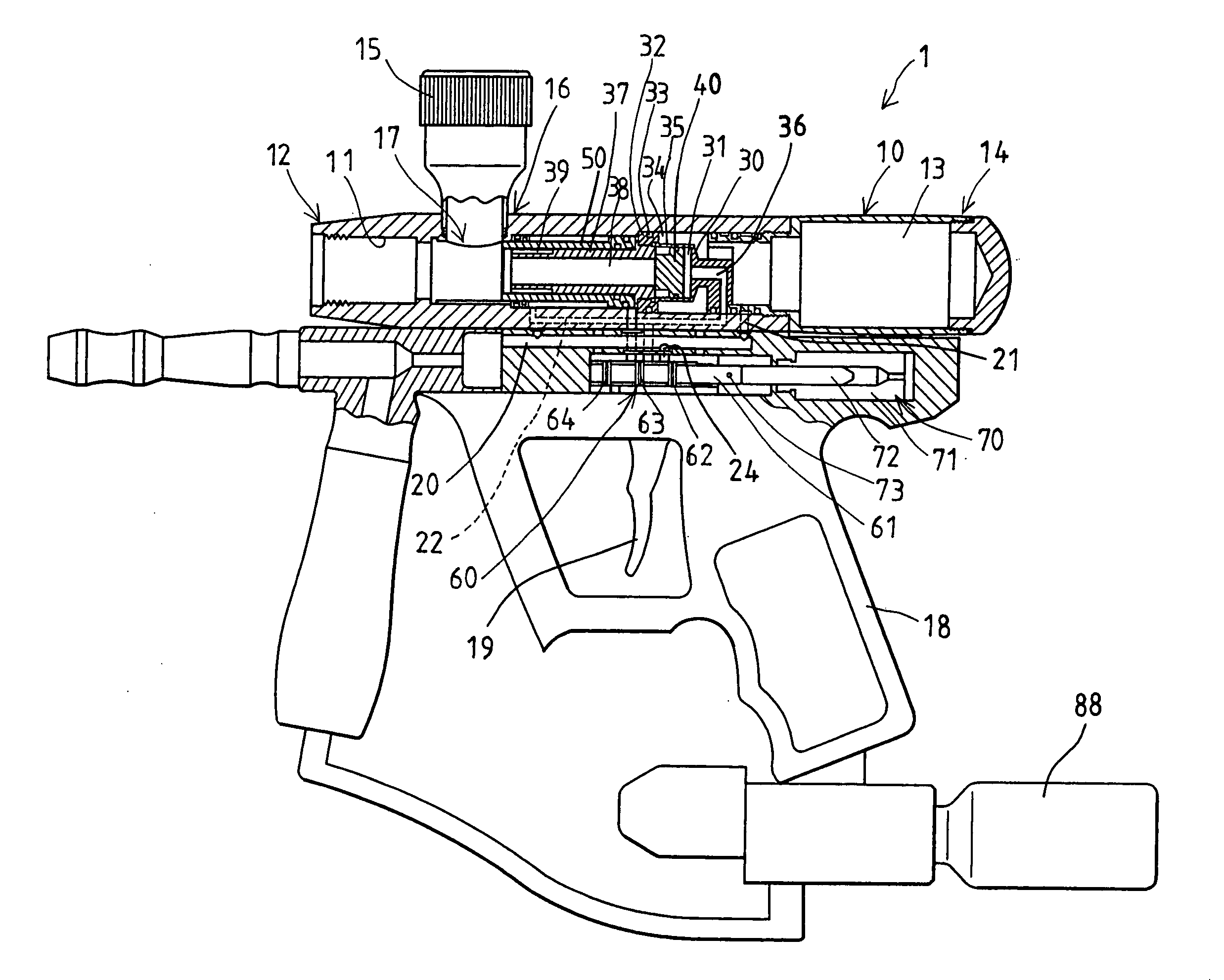
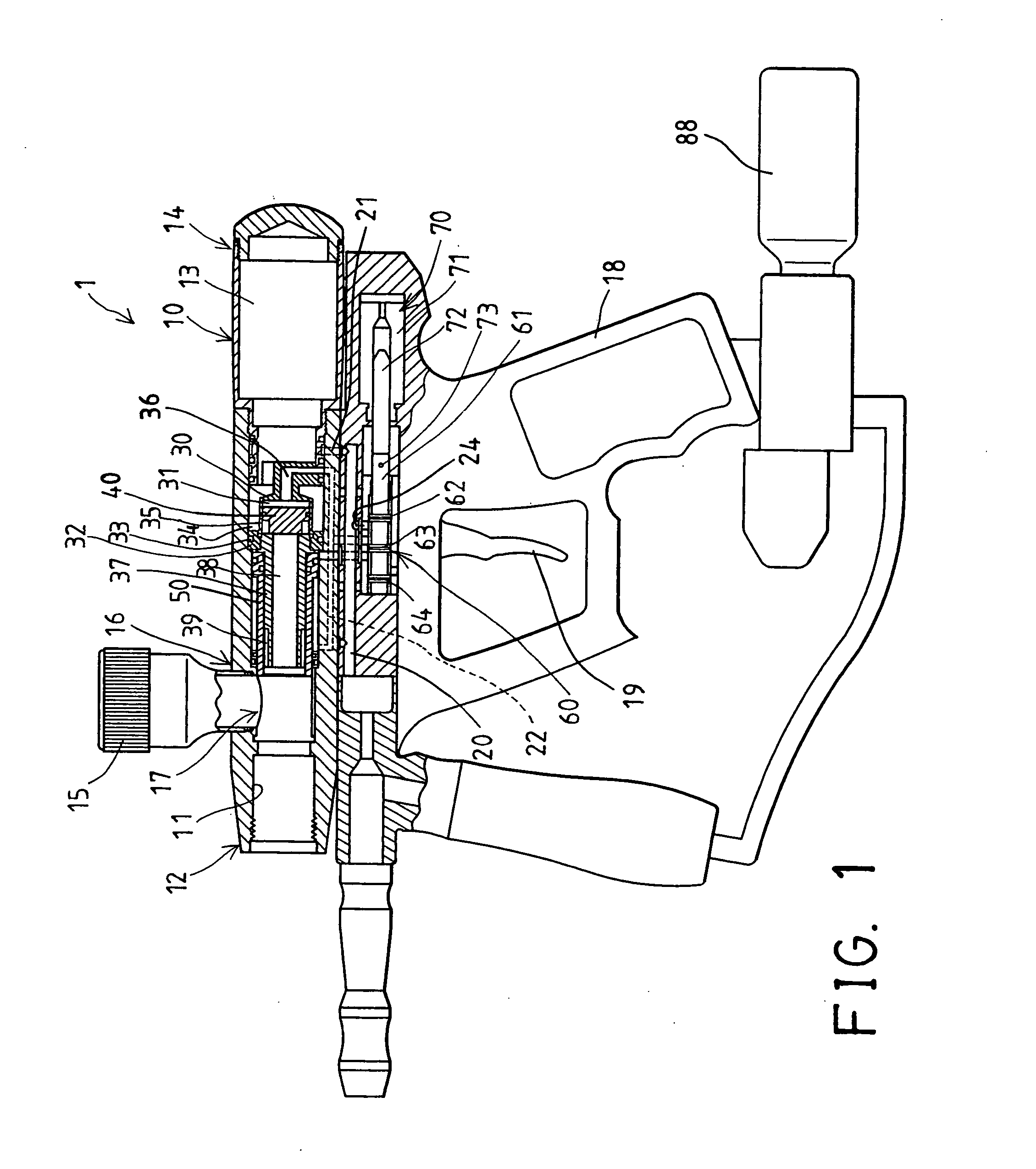
[0008]The primary objective of the present invention is to provide a pneumatic paintball gun including a structure or mechanism for collecting or reusing the pressurized air or gas that has been used for firing the paintball or bullet and thus for effectively using or employing the pressurized air or gas and for economizing the pressurized air or gas.
[0009]The other objective of the present invention is to provide a pneumatic paintball gun including a structure or mechanism for allowing the pressurized air or gas to be completely used for firing the paintball or bullet and thus for allowing the paintball or bullet to be shot for a longer distance.
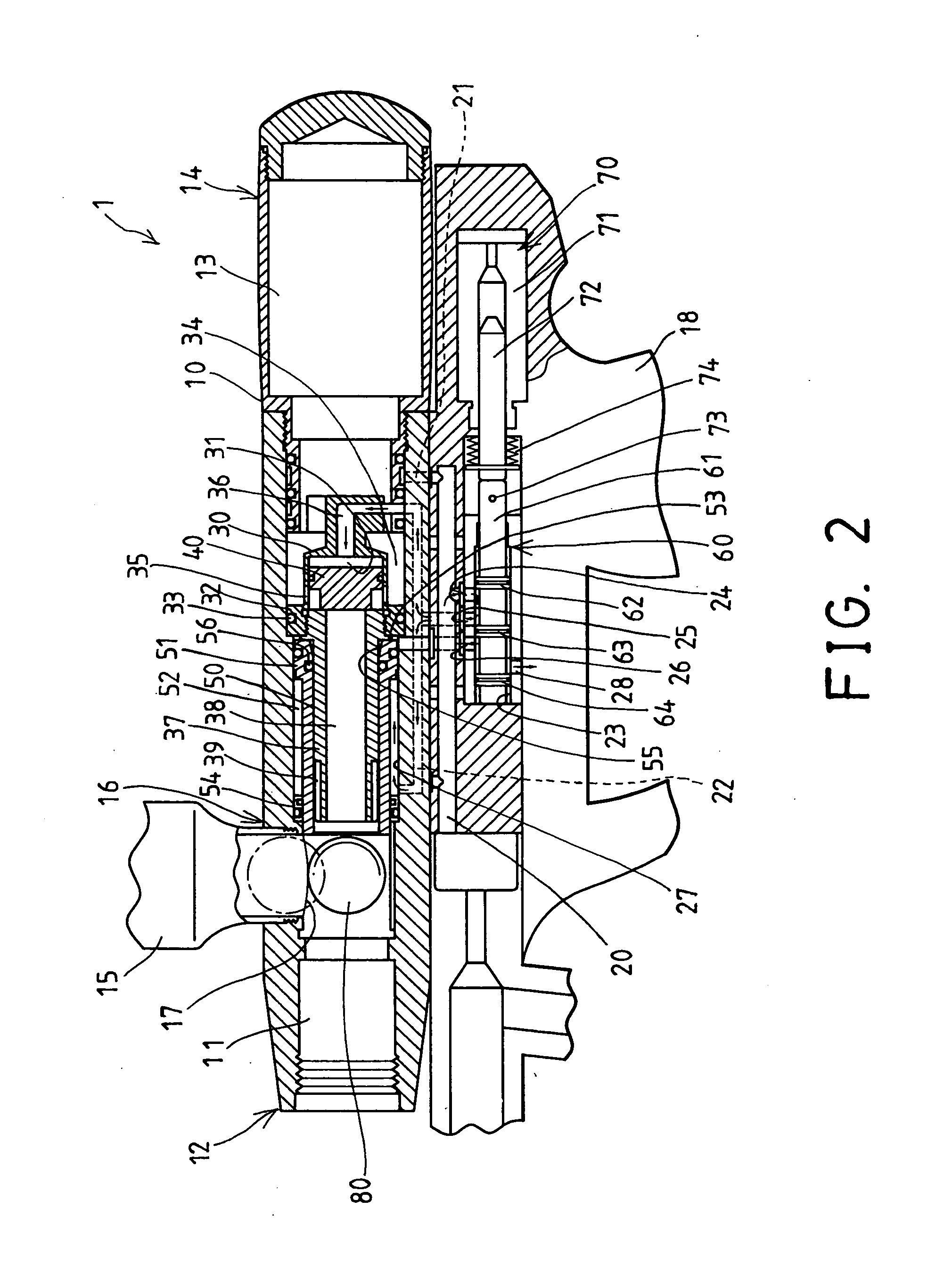
[0014]The casing includes a pipe secured to the casing and located in the inner chamber of the housing, and the pipe includes a bore formed therein and communicating with the control chamber of the casing and the firing chamber of the housing. The piston is movable relative to the casing for selectively engaging with the pipe in order to block the bore of the pipe and to prevent the pressurized gas from flowing into the bore of the pipe and the firing chamber of the housing.

Problems solved by technology

However, normally, the high pressure gas may only be supplied into the firing chamber of the gun body to fire or to propel the paintballs or bullets out of the firing chamber of the gun body and will be discharged after the firing operation, such that a portion of the high pressure gas that is initially supplied into the firing chamber of the gun body will be separated and guided to recover the firing device and / or the loading device and / or the valve device of the typical air gun firing system and such that the high pressure gas may not be completely used to effectively fire or propel the paintballs or bullets and such that the firing or moving distance of the paintballs or bullets will be decreased.

Method used


Image

  • Pneumatic paintball gun
  • Pneumatic paintball gun
  • Pneumatic paintball gun

Examples


Embodiment Construction

[0021]Referring to the drawings, and initially to FIG. 1, a pneumatic paintball gun or bullet gun device 1 in accordance with the present invention comprises a gun body or housing 10 with a gun barrel (not shown) secured to and projected from the forward end of the housing 10. The housing 10 includes a longitudinal or inner firing chamber 11 formed therein, such as formed in the front portion of the housing 10 or of the gun barrel for receiving a paintball or a bullet 80 therein, and a gas storage chamber 13 provided or formed in the rear portion 14 of the housing 10 for receiving a pressurized air or gas therein and for selectively supplying the pressurized air or gas into the firing chamber 11 of the housing 10 in order to selectively fire the paintball or bullet 80 out of the firing chamber 11 of the housing 10.

[0022]A feed tube 15 is attached or coupled to the front or middle portion 16 of the housing 10 and includes a mouth 17 communicating with the firing chamber 11 of the hou...


PUM


Abstract

A gun device includes a housing having a gas supplying passage communicating with a gas storage chamber of the housing for coupling to a pressurized gas supplying source, a feed tube for feeding a bullet into the housing. The pressurized gas supplied into the gas storage chamber of the housing may all be used to fire the bullet. In addition, the pressurized gas supplied into a manifold of the housing may be used to move a cylinder and a piston and may also be recycled and used to fire the bullet such that the bullet may be fired or propelled with a greater quantity of the pressurized gas and thus may be fired or propelled for a longer distance, for economizing the pressurized gas.

Description

BACKGROUND OF THE INVENTION[0001]1. Field of the Invention[0002]The present invention relates to a pneumatic paintball gun, and more particularly to a pneumatic paintball gun including a structure or mechanism for collecting or reusing the pressurized air or gas that has been used for firing the paintball or bullet and thus for effectively using or employing the pressurized air or gas and for economizing the pressurized air or gas.[0003]2. Description of the Prior Art[0004]Typical pneumatic paintball guns or bullet guns comprise a handgun shaped gun body including a hand grip for being held or grasped by the users, and including a loading assembly disposed in the upper portion of the gun body for feeding the paintballs or bullets into the firing chamber of the gun body one by one, and including a firing assembly disposed in the middle or lower portion of the gun body for firing the paintballs or bullets out of the firing chamber of the gun body, and including a high pressure gas con...

Claims


Application Information

Patent Timeline
Patent Type & Authority Applications(United States)
IPC IPC(8): F41B11/00
CPCF41B11/721
Inventor GAN, YIAUGUO
Owner GAN YIAUGUO
Learn More