
Magnetic force sensing device in a brushless motor to enhance magnetic force sensibility of a hall element inside the brushless motor

a brushless motor and sensing device technology, applied in the direction of dynamo-electric components, synchronous machines with stationary armatures and rotating magnets, mechanical energy handling, etc., can solve the problems of weak or decreased resistance between the two corresponding polarities, damage to the efficiency of the motor, etc., to improve the inefficiency of the magnetic force sensing

Inactive Publication Date: 2008-02-28
ADDA
View PDF9 Cites 8 Cited by
  • Summary
  • Abstract
  • Description
  • Claims
  • Application Information

AI Technical Summary

Benefits of technology

[0008]The primary objective of the present invention is to provide a magnetic force sensing device to improve the inefficiency of the magnetic force sensibility of the Hall element.
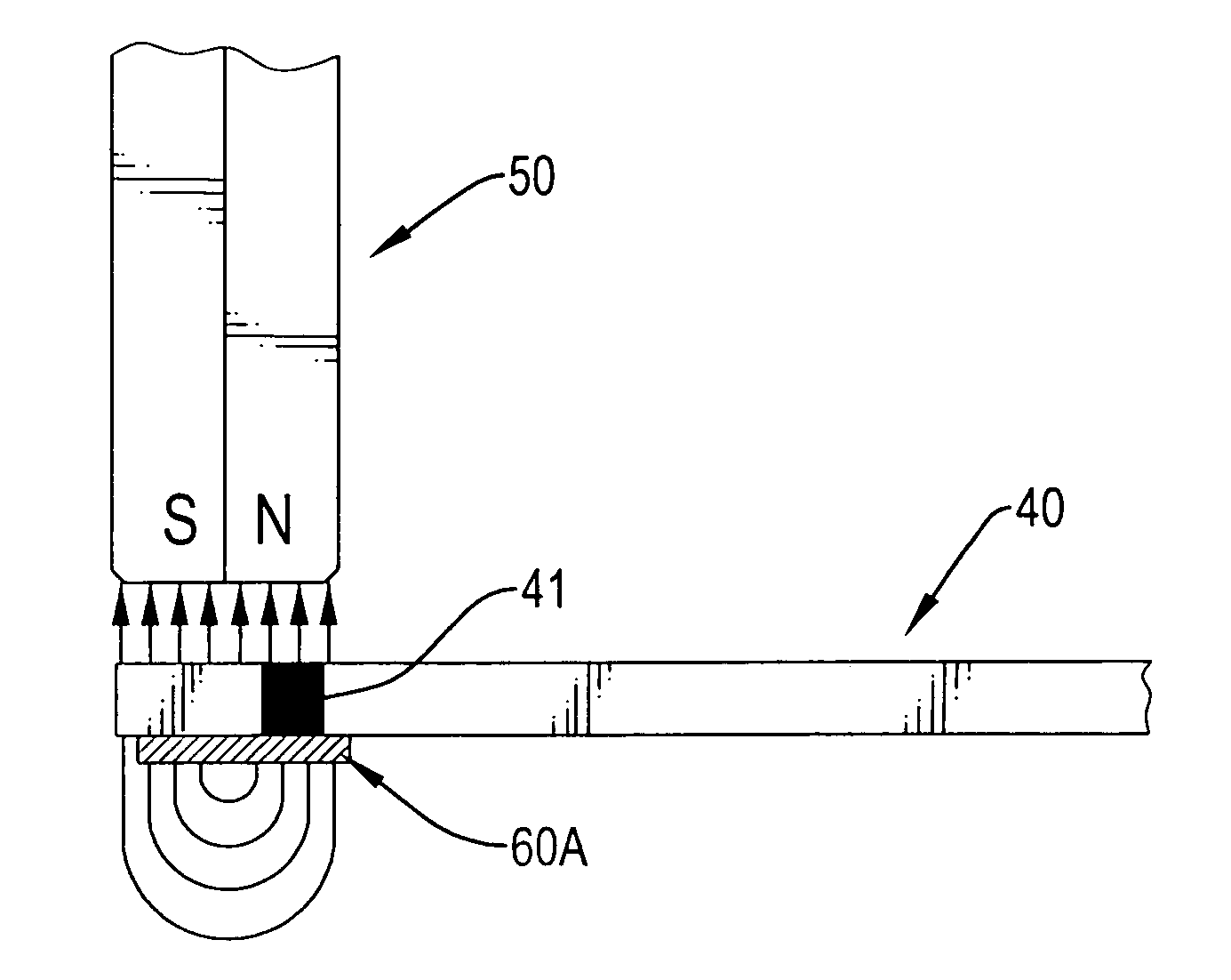
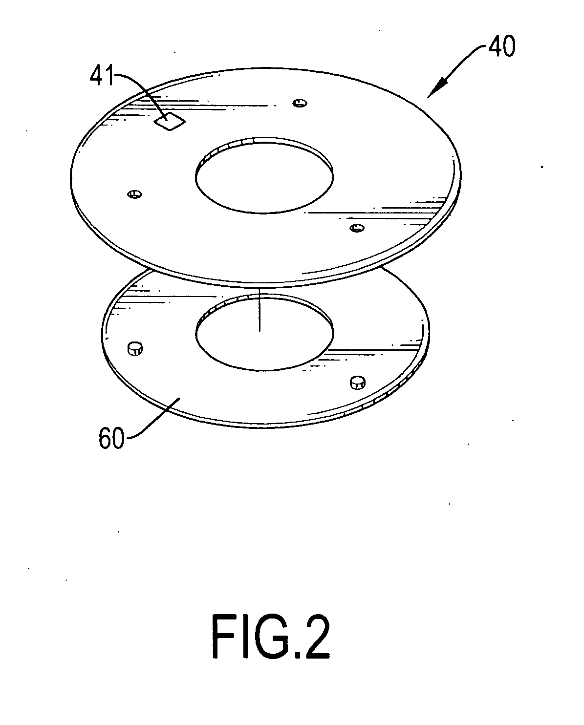
[0009]In order to accomplish the aforementioned objective, the magnetic force sensing device includes a drive circuit board, an annular magnet and a magnetic force conducting plate. The drive circuit board is mounted below the stator and has a Hall element electrically connected to the drive circuit board. The annular magnet is mounted on an inner periphery of the motor casing and the magnetic force conducting plate is provided below the drive circuit board to sandwich the Hall element with the annular magnet. Therefore, due to the existence of the magnetic force conducting plate, the magnetic flux from the annular magnet and the Hall element is increased. Consequently, the distance and strength disadvantages of the conventional structure is obviated and the efficiency of the motor is maintained.

Problems solved by technology

However, due to the distance limitation for magnetic force sensibility of the Hall element and / or strength of the magnetic force from the permanent magnet to the Hall element, the Hall element may not be able to change the induced polarity of the induced magnet in time such that the repelling force between the two corresponding polarities is weak or decreased due to remaining magnetic force between the permanent magnet and the induced magnet of the stator.
Accordingly, the efficiency of the motor is damaged.

Method used


Image

  • Magnetic force sensing device in a brushless motor to enhance magnetic force sensibility of a hall element inside the brushless motor
  • Magnetic force sensing device in a brushless motor to enhance magnetic force sensibility of a hall element inside the brushless motor
  • Magnetic force sensing device in a brushless motor to enhance magnetic force sensibility of a hall element inside the brushless motor

Examples


Embodiment Construction

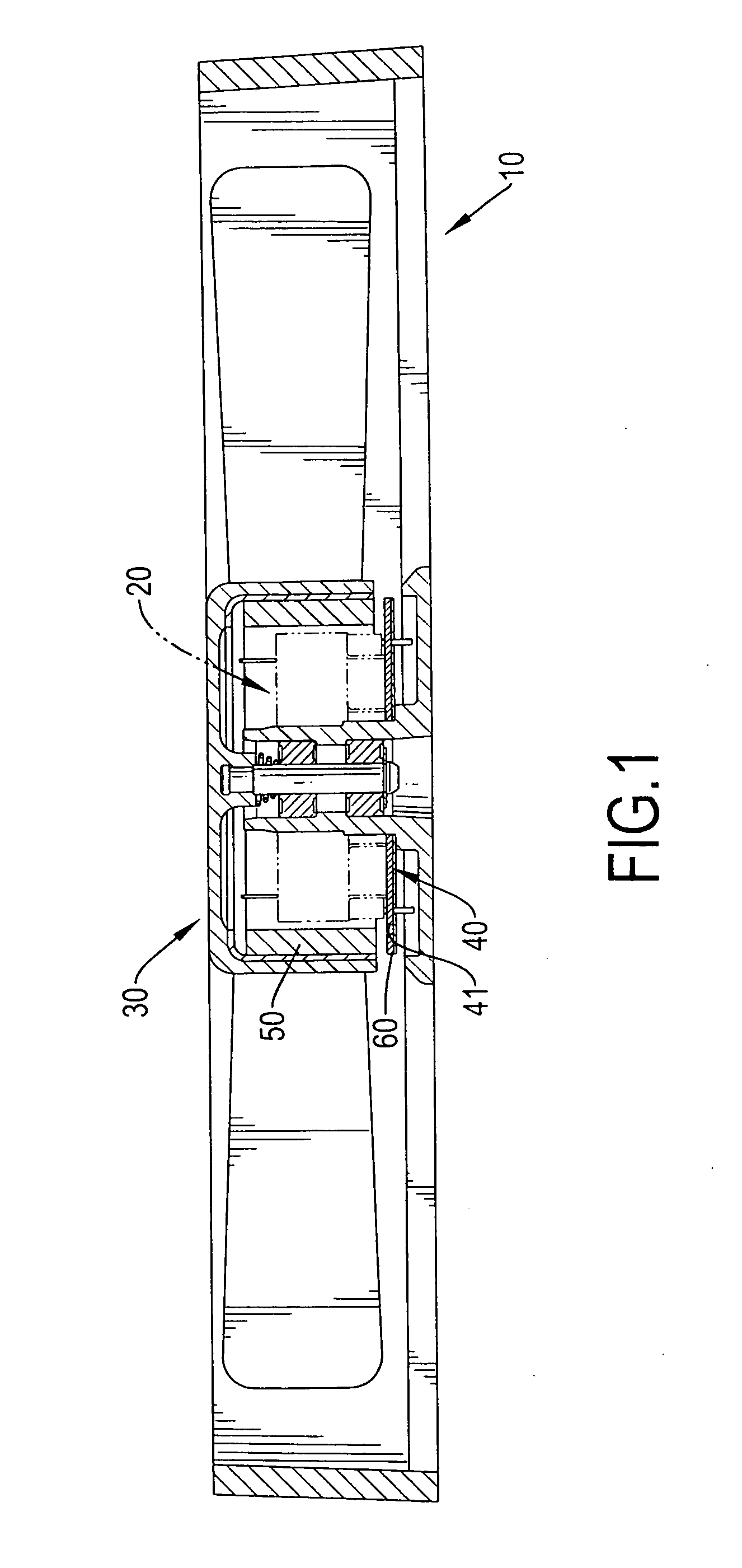
[0016]With reference to FIG. 1, it is noted that the magnetic force sensing device in accordance with the present invention is incorporated with a motor having a casing (10), a stator (20) and a rotor (30) both received inside the casing (10). The stator (20) is mounted inside the casing (10) and having therein a coil. The rotor (30) is rotatably mounted inside the casing (10). The magnetic force sensing device includes a drive circuit board (40), a magnet (50) and a magnetic force conducting plate (60).

[0017]The drive circuit board (40) is mounted in the casing (10) and has a Hall element (41) electrically connected to the drive circuit board (40) and corresponding to the stator (20).

[0018]The magnet (50) is annular and mounted inside a housing of the rotor (30) and outside the stator (20) to keep a distance to an outer periphery of the stator (20). The magnet (50) corresponds to the Hall element (41).

[0019]The magnetic force conducting plate (60) is mounted below the drive circuit...


PUM


Abstract

A magnetic force sensing device for a brushless motor includes a drive circuit board mounted inside the casing and located below the stator, a Hall element electrically connected to the drive circuit board, an annular magnet mounted on a rotor casing and located outside the stator, and a magnetic force conducting plate having an area larger than that of the Hall element and being mounted below the drive circuit board to sandwich the Hall element with the annular magnet. Due to the addition of the magnetic force conducting plate below the magnet, magnetic flux from the magnet to the Hall element is increased.

Description

BACKGROUND OF THE INVENTION[0001]1. Field of the Invention[0002]The present invention relates to a magnetic force sensing device, and more particularly to a magnetic force sensing device in a brushless motor so as to enhance magnetic force sensibility of a Hall element inside the brushless motor.[0003]2. Description of the Prior Art[0004]Inside a brushless motor, there is provided with a drive circuit board, a stator mounted on the drive circuit board and a rotor rotatably mounted outside the stator. The drive circuit board has circuitry formed thereon and a Hall element which is positioned on top of the drive circuit board and electrically connected to the drive circuit board. The stator has a coil which is also electrically connected to the drive circuit board. An annular permanent magnet is mounted inside a circular casing of the rotor and has N-S polarity corresponding to the Hall element on the drive circuit board.[0005]When in application, the Hall element on the drive circuit...

Claims


Application Information

Patent Timeline
Patent Type & Authority Applications(United States)
IPC IPC(8): H02K7/00H02K11/00H02K21/12
CPCH02K29/08
Inventor HSIEH, HSIN-MAOCHEN, HSIN-PUCHEN, WAN-YANG
Owner ADDA
Learn More