Pwm method and apparatus, and light source driven thereby

a technology of pulse width and modulation method, which is applied in the field of pulse width modulation (pwm) method and apparatus, and the direction of pulse technique, process and machine control, etc., can solve the problems of prohibitively expensive and impractical for most lighting applications, and achieve adequate means for generating pwm signals

Inactive Publication Date: 2008-02-28
KONINKLIJKE PHILIPS ELECTRONICS NV
View PDF1 Cites 80 Cited by
  • Summary
  • Abstract
  • Description
  • Claims
  • Application Information

AI Technical Summary

Benefits of technology

[0021]In accordance with another aspect of the present invention, there is provided a light source comprising: one or more light-emitting elements; and a driving system for driving each one of said one or more light-emitting elements at a given frequency and at a respective relative intensity, said driving system comprising: a generating module for generating, for each of said one or more light-emitting element

Problems solved by technology

The high resolution PWM signals required to provide such control, particularly at switching frequencies selected to minimise the above and other such undesirable frequency-dependent effects, generally require the use of high speed microprocessors, which can be prohibitively expensive and can be impr

Method used


Image

  • Pwm method and apparatus, and light source driven thereby
  • Pwm method and apparatus, and light source driven thereby
  • Pwm method and apparatus, and light source driven thereby

Examples


example 1

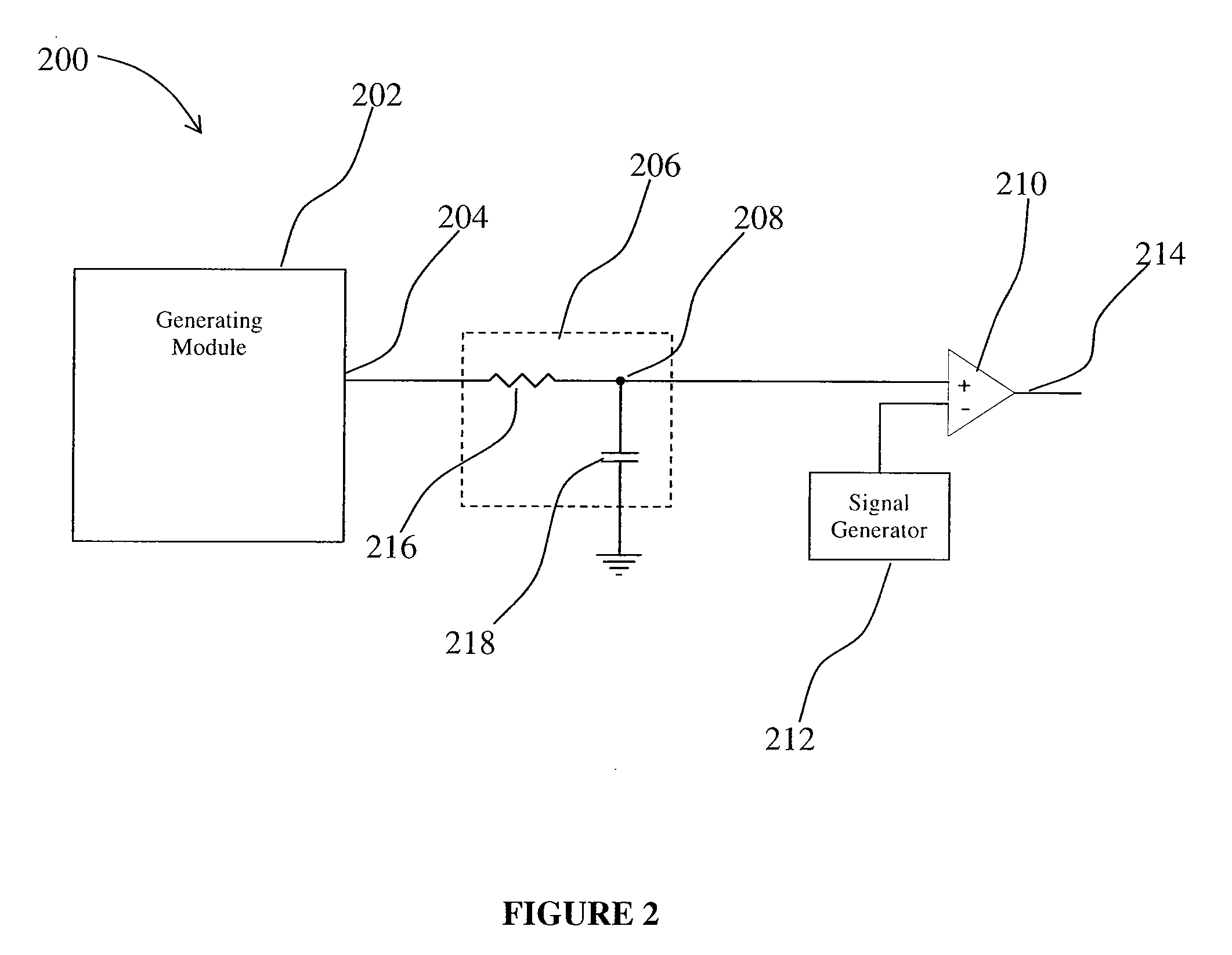
[0072]With reference to FIG. 2, an apparatus for generating a PWM signal, generally referred to using the numeral 200, and in accordance with one embodiment of the present invention, will now be described. The apparatus 200 generally comprises a generating module 202 for generating at output 204 a first PWM signal having a desired resolution and a first frequency. The first PWM signal is then converted by a converting module 206 to generate an analog signal at node 208 indicative of the duty-cycle of the first PWM signal. The analog signal is then provided as input to a comparing module 210, such as a high speed comparator or the like, adapted to compare the analog signal to a reference signal having a desired frequency (illustratively provided by signal generator 212), and thereby generate a second PWM signal substantially having the desired frequency and resolution at output 214.

[0073]The generating module 202 may comprise a microprocessor or the like, adapted to generate the firs...

example 2

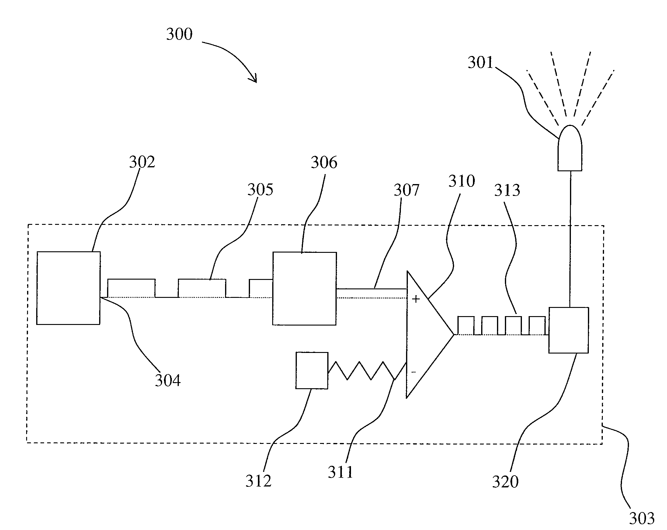
[0076]With reference now to FIG. 3, a light source driven by a PWM signal, generally referred to using the numeral 300, and in accordance with one embodiment of the present invention, will now be described. The light source 300 generally comprises a light-emitting element 301 and a driving system 303 therefor.

[0077]In general, the driving system 303 comprises a generating module 302 for generating at output 304 a first PWM signal 305 having a desired resolution and a first frequency. The first PWM signal is then converted by a converting module 306 to generate an analog signal 307 indicative of the duty-cycle of the first PWM signal 305. The analog signal 307 is then provided as input to a comparing module 310, such as a high speed comparator or the like, adapted to compare the analog signal 307 to a reference waveform, as in triangle or saw tooth signal 311, having a desired frequency (illustratively provided by signal generator 312). By comparing the analog signal 307 with the ref...

example 3

[0083]With reference now to FIG. 4, a light source driven by a PWM signal, generally referred to using the numeral 400, and in accordance with one embodiment of the present invention, will now be described. The light source 400 generally comprises three light-emitting elements 401, or groups or arrays thereof, and a driving system 403 therefor.

[0084]In general, the driving module 403 comprises a generating module 402 for generating at output 404 respective first PWM signals 405 having a substantially same desired resolution. In general, a first PWM signal 405 is generated for each light-emitting element 401, or group or array of a given type or colour of light-emitting elements, and communicated via a respective channel. Each PWM signal 405 is then converted by a converting module 406 to generate a respective analog signal, as in signal 407, indicative of a duty-cycle thereof. The respective analog signals 407 are then provided as input to a comparing module 410, such as one or more...


PUM


Abstract

The present invention provides a pulse-width modulation (PWM) method and apparatus, and light source driven thereby. In particular, the present invention provides a PWM method and apparatus for generating a PWM signal having a desired resolution and frequency using generating means traditionally limited to providing PWM signals having a lower resolution and/or frequency. The PWM method and apparatus of the present invention may be used in a number of applications where a relatively high PWM resolution and/or frequency is desired, but where selection of generating means for generating such PWM signals is relatively limited by cost and/or other such constraints. For example, a PWM signal generated by the method and apparatus of the present invention may be useful in accurately controlling the output of the one or more light-emitting elements of a light source, namely to control a dimming and/or colour level thereof, without using driving components that may be relatively costly for the application at hand.

Description

CROSS-REFERENCE TO RELATED APPLICATIONS[0001]This application claims benefit of United States provisional patent application Ser. No. 60 / 823,732, filed Aug. 28, 2006, which is herein incorporated by reference.BACKGROUND OF THE INVENTION[0002]1. Field of the Invention[0003]The present invention pertains to the fields of lighting and signal modulation and, in particular, to a pulse-width modulation (PWM) method and apparatus, and light source driven thereby.[0004]2. Description of the Related Art[0005]Advances in the development and improvements of the luminous flux of light-emitting devices such as solid-state semiconductor and organic light-emitting diodes (LEDs) have made these devices suitable for use in general illumination applications, including architectural, entertainment, and roadway lighting. Light-emitting diodes are becoming increasingly competitive with light sources such as incandescent, fluorescent, and high-intensity discharge lamps. Also, with the increasing selectio...

Claims


Application Information

Patent Timeline
IPC IPC(8): H05B37/02H03K7/08H05B44/00
CPCH03K7/08Y02B20/346H05B33/086H05B33/0818H05B45/20Y02B20/30
Inventor ROBINSON, SHANE P.
Owner KONINKLIJKE PHILIPS ELECTRONICS NV
Why Eureka
Try Eureka