
Battery device, electronic apparatus, and battery system

Inactive Publication Date: 2008-02-28
SONY CORP
View PDF21 Cites 25 Cited by
  • Summary
  • Abstract
  • Description
  • Claims
  • Application Information

AI Technical Summary

Benefits of technology

[0017]A battery device according to an embodiment of the present invention having such a configuration may provide a type discrimination portion for a new battery device with a simple structure and may be commonly used for multiple types of an electronic apparatus having different mounting systems. An electronic apparatus according to an embodiment of the present invention may provide a type discrimination portion for a new battery device with a simple structure, and a battery device mounted on a mounting portion of the electronic apparatus to supply power may be commonly used for multiple types of the electronic apparatus having different mounting systems. Further, a battery system according to an embodiment of the present invention including a combination of the battery device and the electronic apparatus described above may provide a battery system having advantages of the battery device and the electronic apparatus.

Problems solved by technology

As a result, when a new battery device is developed, it may be necessary to increase the number of the steps in the recess of the battery device and provide a protrusion corresponding to the recess in the mounting portion of the electronic apparatus, and thus the recess of the battery device and the protrusion of the mounting portion have complicated shapes.

Method used


Image

  • Battery device, electronic apparatus, and battery system
  • Battery device, electronic apparatus, and battery system
  • Battery device, electronic apparatus, and battery system

Examples


example 1

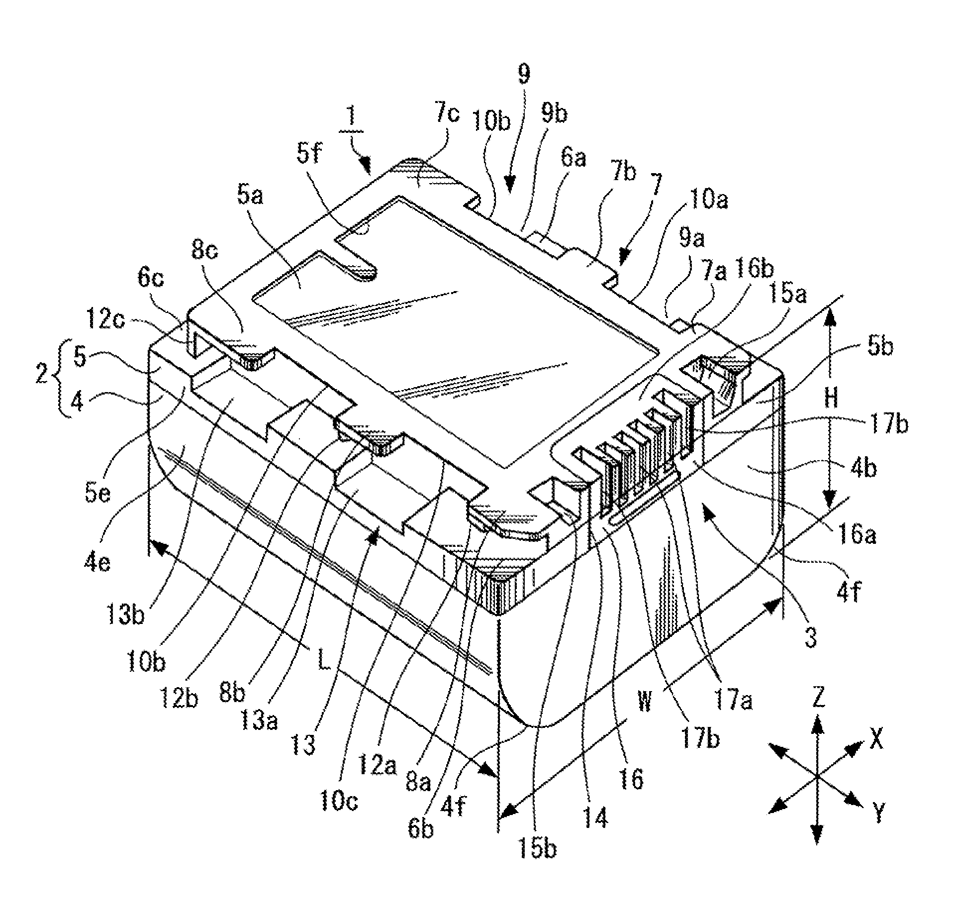
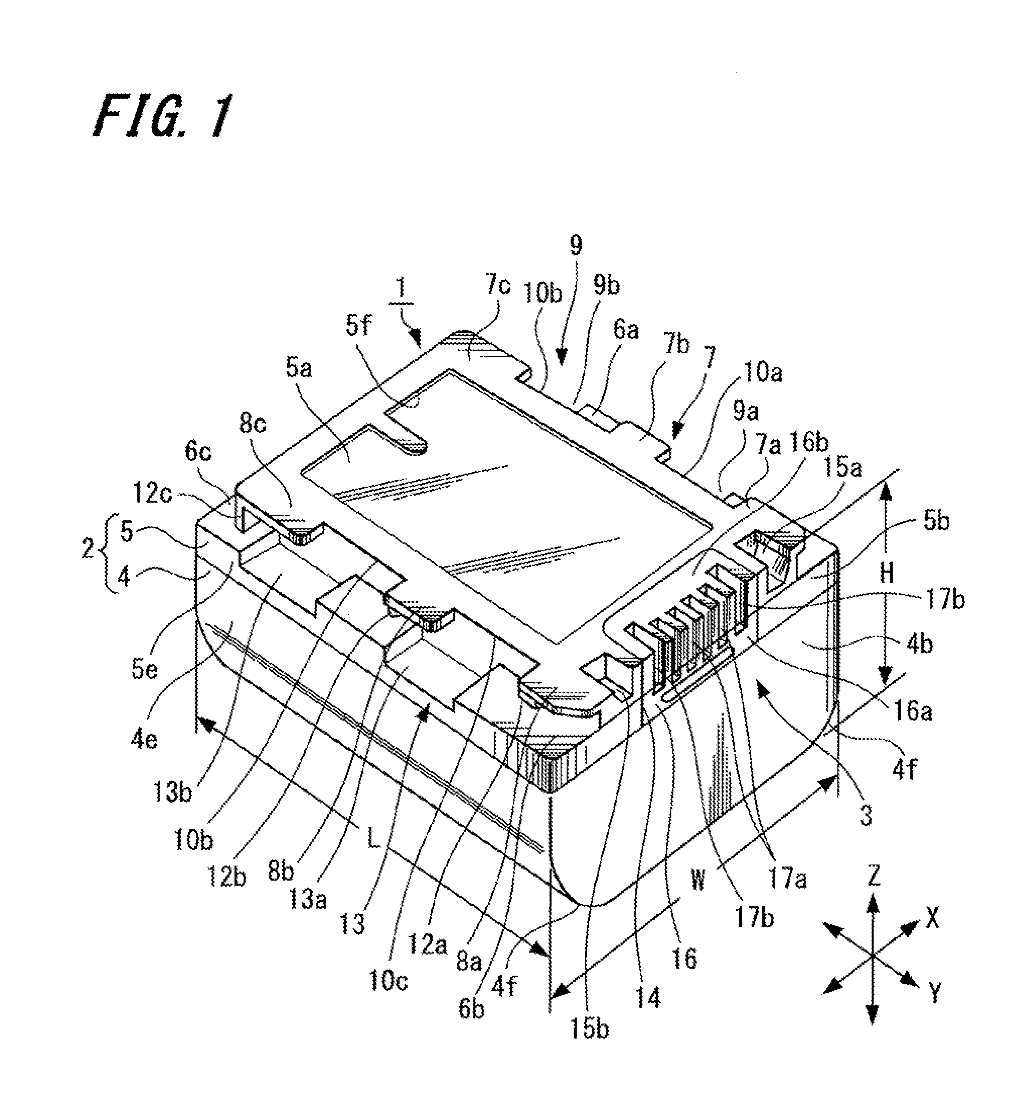
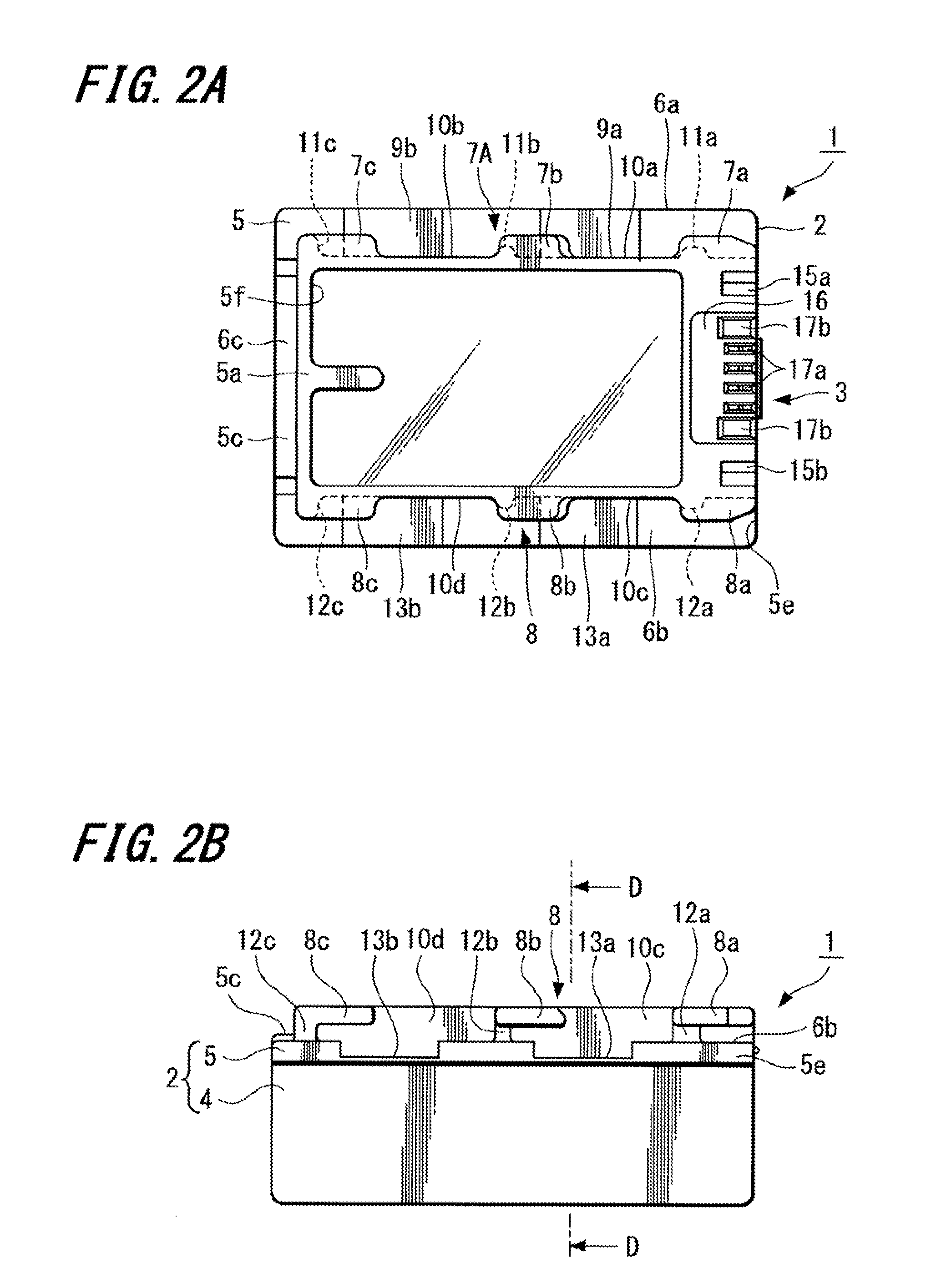
[0038]First, a first example of a battery device according to an embodiment of the present invention will be described with reference to FIGS. 1 to 3. The battery device 1 includes: a battery enclosure 2 formed with a hollow enclosure; a battery cell and a control circuit board (not shown) provided inside the battery enclosure 2; and a battery side output terminal 3 provided in the battery enclosure 2.

[0039]As shown in FIG. 1, the battery enclosure 2 shown in this example is formed as an approximately rectangular parallelepiped block-shaped container having a dimension L in a longitudinal direction Y, a dimension W in a crosswise direction X at right angles to the longitudinal direction Y, and a dimension H in a height direction Z at right angles to the longitudinal direction Y and the crosswise direction X. In this example, the dimensions of the battery enclosure 2 (length L, width W, and height H) are set to have a relation of: length L>width W>height H. However, a shape of a batt...


PUM


Abstract

Disclosed is a battery device including a battery enclosure incorporating a battery cell. The battery device further includes an output terminal that outputs power of the battery cell. The battery enclosure includes a first surface, a second surface, a first step surface, a second step surface, a first engaging portion, a second engaging portion, a first groove, and a second groove formed in the second step surface and the second engaging portion, and a recess is provided in at least one of the first step surface and the second step surface.

Description

CROSS REFERENCES TO RELATED APPLICATIONS[0001]The present invention contains subject matter related to Japanese Patent Application JP 2006-230797 filed in the Japanese Patent Office on Aug. 28, 2006, the entire contents of which being incorporated herein by reference.BACKGROUND OF THE INVENTION[0002]1. Field of the Invention[0003]The present invention relates to a battery device used as a portable power source, an electronic apparatus in which the battery device is detachably mounted and used, and a battery system including a combination of the electronic apparatus with the battery device.[0004]2. Description of the Related Art[0005]Japanese Unexamined Patent Application Publication No. 2000-243365 discloses an example of a battery device of the related art as a portable power source. Japanese Unexamined Patent Application Publication No. 2000-243365 discloses a battery pack in which a rechargeable battery cell used as a power source for an electronic apparatus is stored; a battery ...

Claims


Application Information

Patent Timeline
IPC IPC(8): H01M2/02H01M50/202H01M50/244H01M50/296
CPCY02E60/12H01M2/1066H01M2220/30Y02E60/10H01M50/202H01M50/296H01M50/244H01M50/103
Inventor HARA, MIEKOTAKESHITA, TOSHIOMIYAJIMA, YOICHISATO, HIROAKIWATANABE, TOMONORIKAMAYA, NAOKI
Owner SONY CORP
Learn More