Electrical connector assembly with reduced crosstalk and electromaganetic interference

Inactive Publication Date: 2008-02-28
HON HAI PRECISION IND CO LTD
View PDF6 Cites 14 Cited by
  • Summary
  • Abstract
  • Description
  • Claims
  • Application Information

AI Technical Summary

Benefits of technology

[0009]Accordingly, the object of the present invention is to provide an electrical connector assembly with reduced cross-talk and electro magnetic interference.

Problems solved by technology

This was costly to the manufacturers and consumers alike, and with each new digital standard, rendered another expensive piece of electronic equipment obsolete.
The promulgation of digital standards in the computing and consumer electronics industries, including HDMI, HDTV, and DVI has created a problem for computer monitor and video card manufacturers.
The VGA analog interface cannot fully accommodate the rich, multimedia signals that arise from products meeting these standards.
However, detailed structures of the UDI connector are not provided, the UDI connector still has room to be improved for achieving perfect signal transmission with compact size.

Method used


Image

  • Electrical connector assembly with reduced crosstalk and electromaganetic interference
  • Electrical connector assembly with reduced crosstalk and electromaganetic interference
  • Electrical connector assembly with reduced crosstalk and electromaganetic interference

Examples


Embodiment Construction

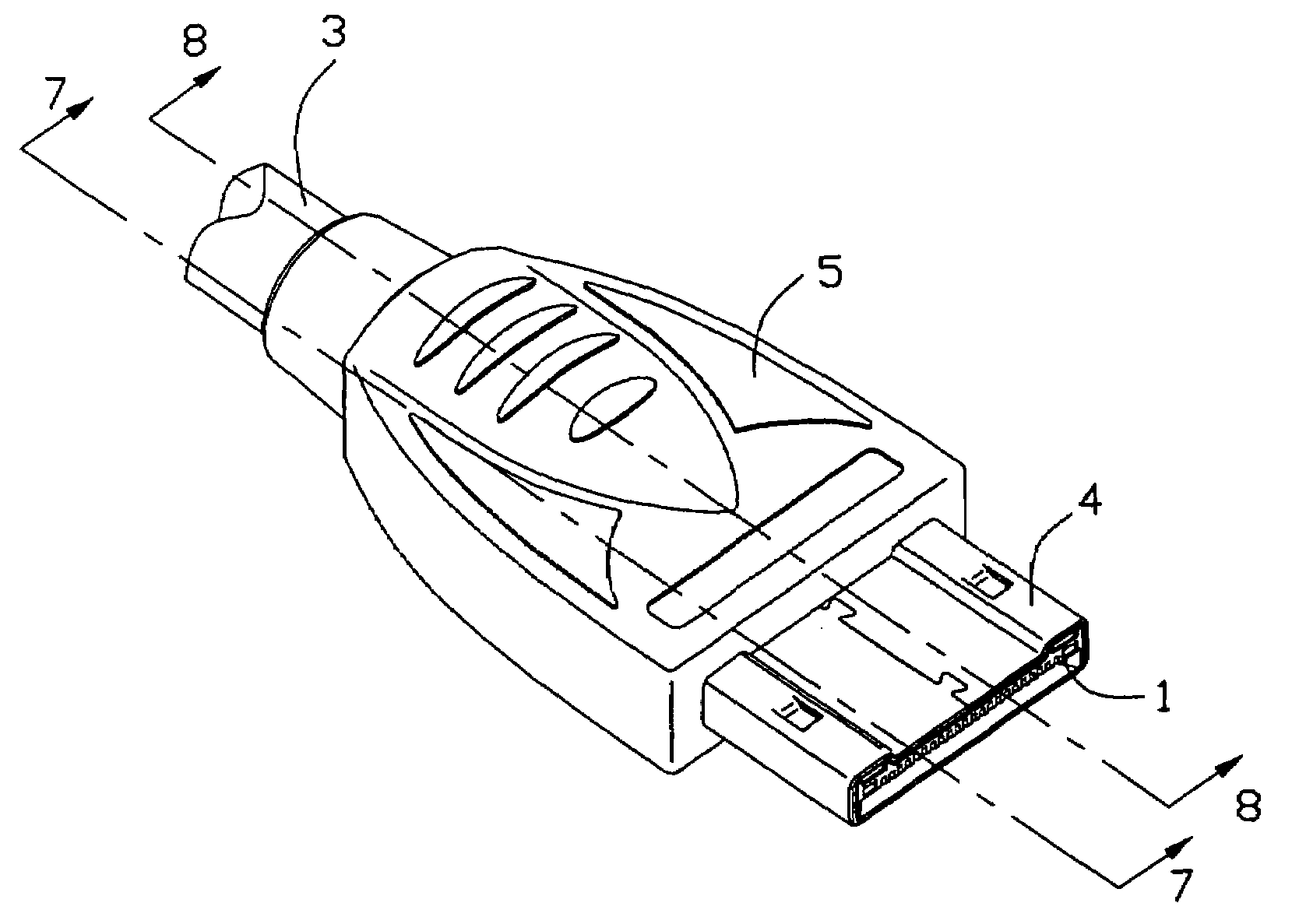
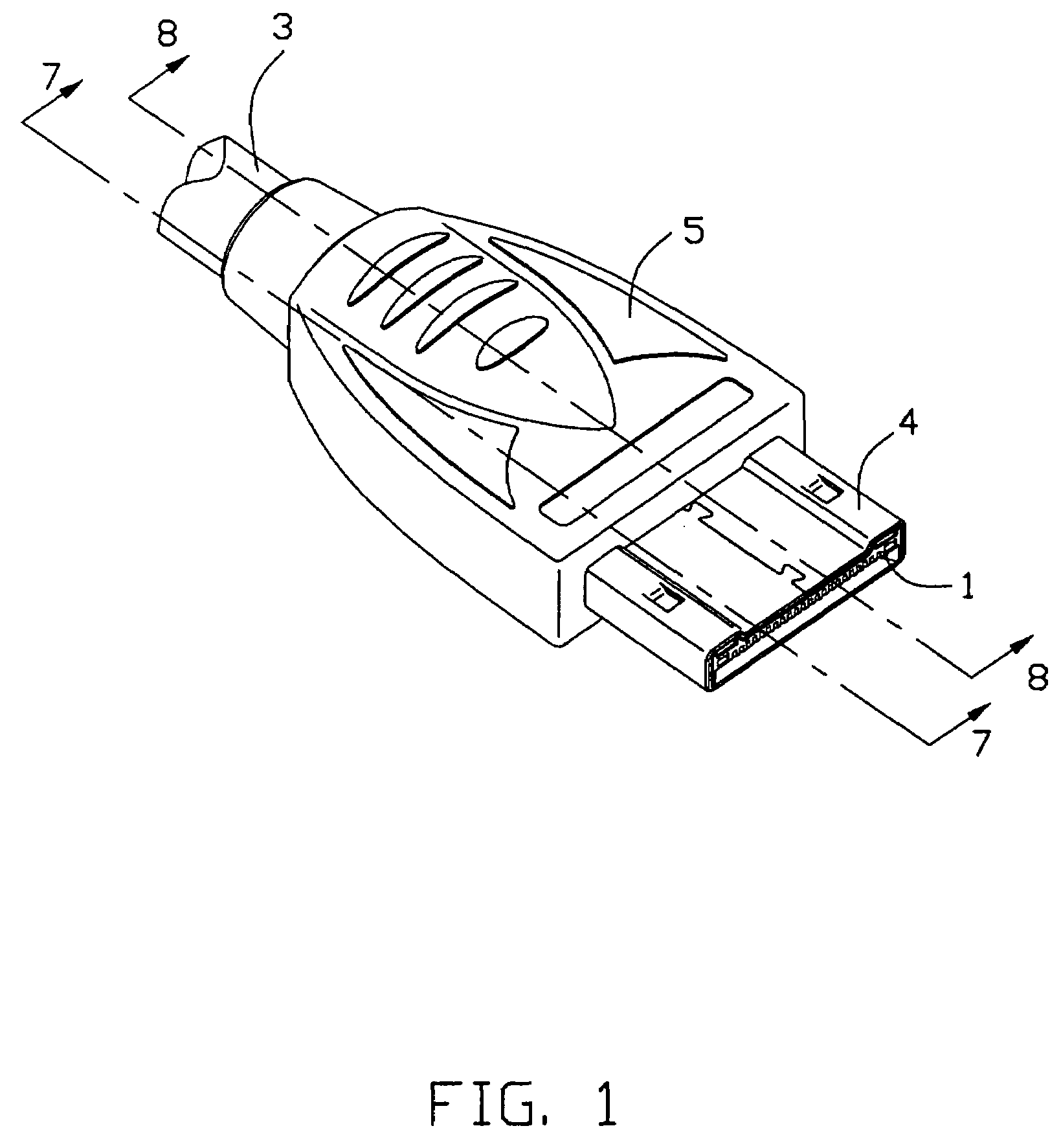
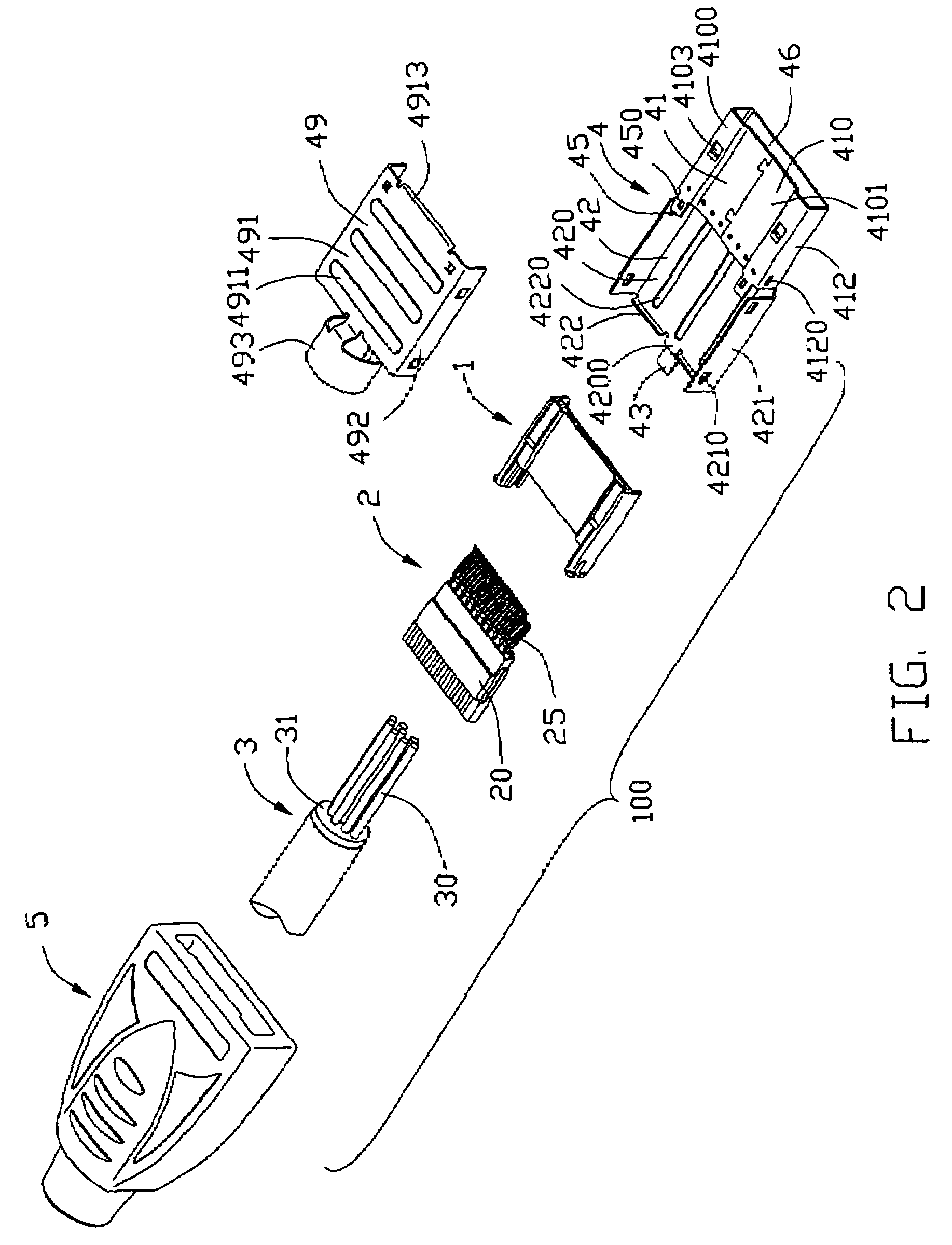
[0020]Referring to FIGS. 1-3, an electrical connector assembly 100 in accordance with the present invention defines a mating direction and a mating interface, and comprises an insulative housing 1, a terminal block assembly 2 attached to the insulative housing 1, a cable 3 electrically connected to the terminal block assembly 2, a metal shell 4 surrounding the insulative housing 1, and a protecting cover 5 partially enclosing the metal shell 4 and the front end of the cable 3.

[0021]Referring to FIGS. 2-5, the insulative housing 1 defines a base portion 10, and a pair of connecting portions 11 unitarily formed with and rearwardly extending from the base portion 10 along the mating direction. The insulative housing 1 is formed of an upper wall 12, a lower wall 13 extending parallel to the upper wall 12 and being shorter than the upper wall 12 and a pair of lateral walls 14 extending between the upper and lower walls 12, 13. The upper, lower and lateral walls 12, 13, 14 together define...


PUM


Abstract

An electrical connector assembly (100) includes an insulative housing (1), a terminal block assembly (2) assembled to the insulative housing (1) and a cable (3) electrically connecting with the terminal block assembly (2). The insulative housing (1) defines a mating direction and a receiving chamber (15). The terminal block assembly (2) includes a number of first and second terminals (26, 28) and an inserting housing (20) insert-molded with the terminals (26, 28). The first and second terminals (26, 28) are divided into two rows and each having a tail portion (261, 281), an interconnecting portion (262, 282) and a contacting portion (263, 283). The contacting portions (263, 283) of the first terminals (26) and the second terminals (28) extend out of the inserting housing (20) along the mating direction and are located in the same plane.

Description

CROSS-REFERENCE TO RELATED APPLICATION [0001]This application is related to U.S. patent application Ser. No. 11 / 481,672, filed on Jul. 5, 2006, and entitled “ELECTRICAL CONNECTOR ASSEMBLY HAVING IMPROVED SHELL”, which has the same applicant and assignee as the present invention. The disclosure of related application is incorporated herein by reference.BACKGROUND OF THE INVENTION[0002]1. Field of the Invention[0003]The present invention relates generally to an electrical connector assembly, and more particularly to an electrical connector assembly for transmitting high-speed signals between two electrical devices.[0004]2. Description of Related Arts[0005]In the days of analog, VGA and S-VGA were the only interfaces required for computer displays. In the last several years, the PC and Consumer Electronics (CE) industries have developed a cornucopia of standards designed to support every type of digital signal that has been developed. Manufacturers have worked very hard to address ever...

Claims


Application Information

Patent Timeline
IPC IPC(8): H01R13/648
CPCH01R24/62H01R2107/00H01R13/6593H01R13/6474H01R13/6583H01R13/6461
Inventor WU, JERRY
Owner HON HAI PRECISION IND CO LTD
Why Eureka
Try Eureka