Electrical connector

a technology of electrical connectors and connectors, which is applied in the direction of electrical apparatus, coupling device connections, coupling/disengagement of coupling parts, etc., can solve the problems of difficult installation of connectors into cable harnesses, and achieve the effect of convenient and economical manufacture and installation

Active Publication Date: 2008-02-28
KOSTAL KONTAKT SYST
View PDF7 Cites 8 Cited by
  • Summary
  • Abstract
  • Description
  • Claims
  • Application Information

AI Technical Summary

Benefits of technology

[0007]An object of the present invention includes an electrical connector which allows current-free and / or voltage-free joining of an electrical high-load connection(s) and which is easily and economically manufactured and installed while avoiding the above-noted disadvantages.
[0012]The first connector part includes a first HL housing and a first LL housing. The first HL housing contains a first set of electrical HL contacts and the first LL housing contains a first set of electrical LL contacts. The interior of the first HL housing is divided into chambers for respectively holding the HL contacts such that the HL contacts are insulated from one another. This insulation is advantageous when terminal lines connected to the HL contacts conduct high voltages. The HL contacts have a sufficiently large cross-section for accommodating high-current applications.
[0016]An electrical connection with HL terminal lines of the HL connection is established or separated via the LL connection by a power control circuit such as a relay or an electronic circuit breaker. The HL connection is not established until the LL contacts are joined together in both LL housings of both connector parts. As described above, the first LL housing is movably connected to the first HL housing of the first connector part and the second LL housing is fixedly connected to the second HL housing of the second connector part. As a result, the first and second LL housings are respectively situated on their associated HL housing such that the LL connection is not closed until the HL housings are completely joined to one another.
[0017]Accordingly, hazardous high voltages on the HL contacts are prevented when the connector parts are not connected to one another, and high current flow through the HL contacts is prevented when the connector parts are not yet completely connected to one another.

Problems solved by technology

It is a problem if electrical feed lines for an electrical high-load connection(s) and an electrical low-load connection(s) are supplied to an electrical connector in parallel as the connector is therefore situated at the end point of the feed lines making it difficult to insert the connector into a cable harness to be installed.

Method used


Image

  • Electrical connector
  • Electrical connector
  • Electrical connector

Examples


Embodiment Construction

)

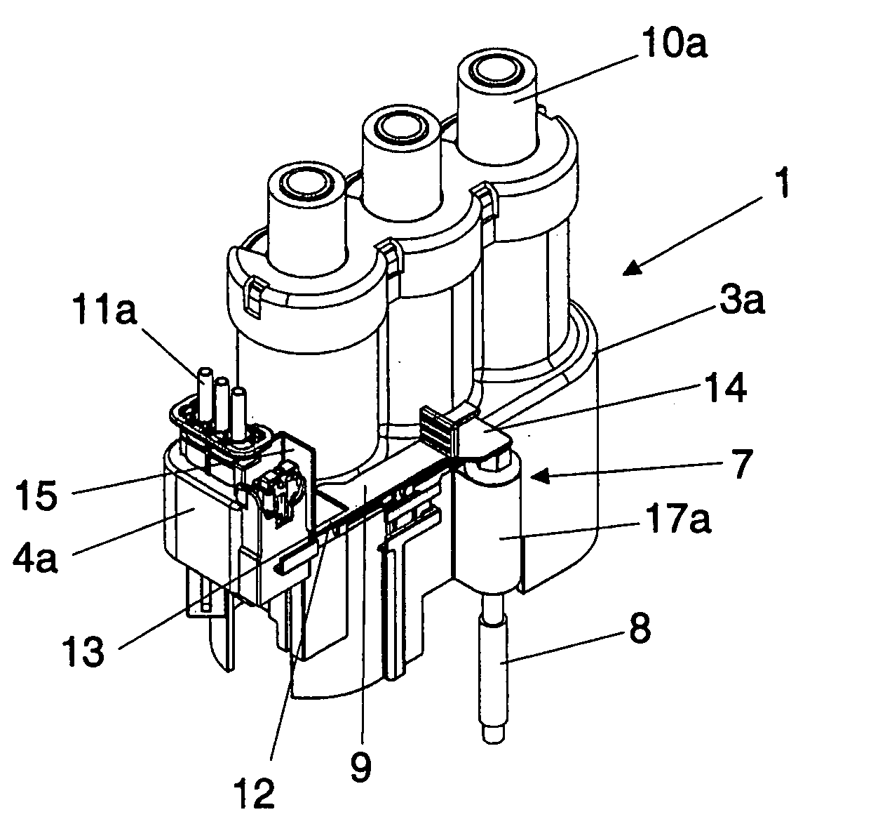
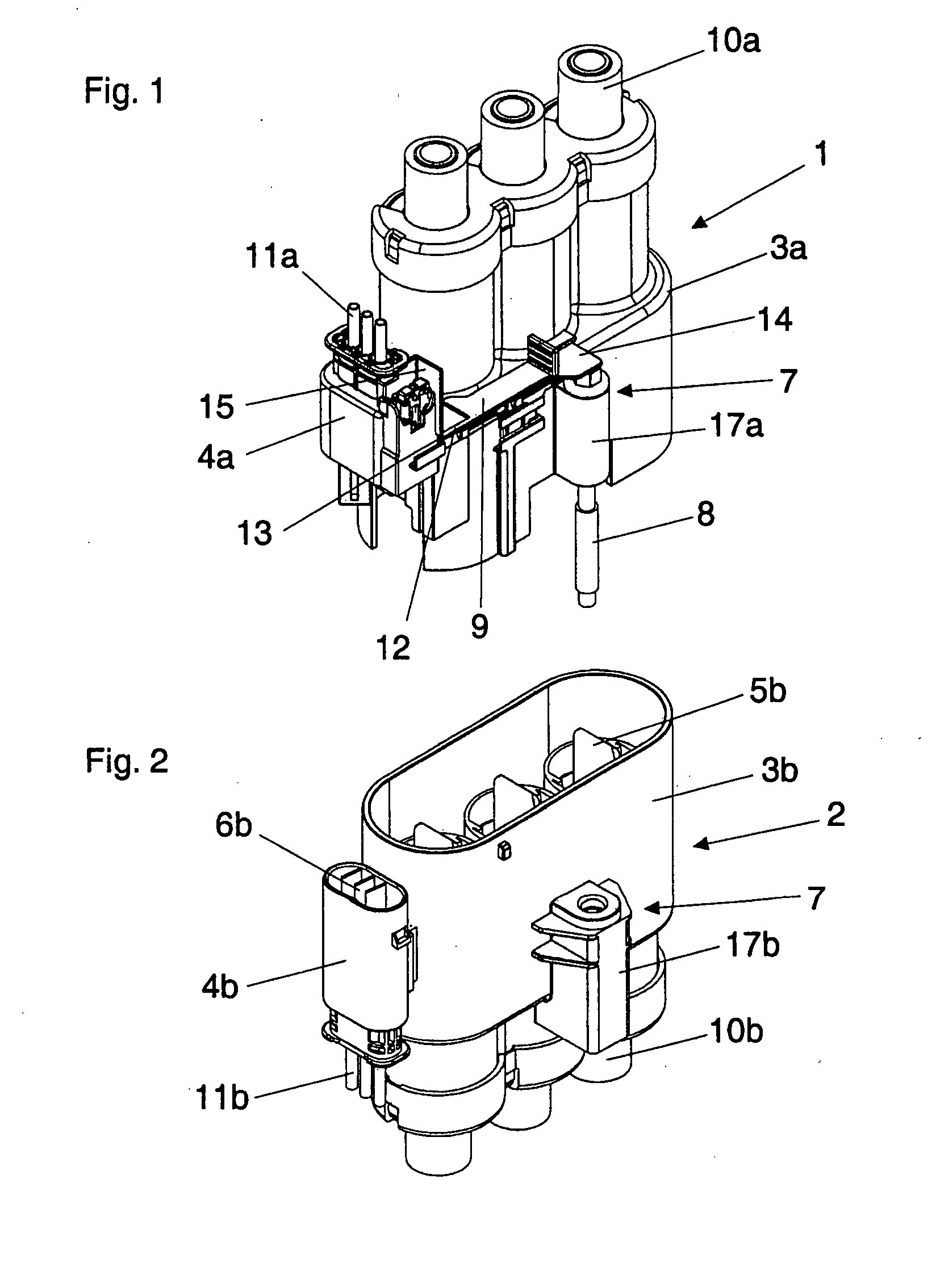
[0026]Referring now to FIGS. 1 and 2, a first plug-in connector part 1 and a second plug-in connector part 2 of an electrical connector in accordance with an embodiment of the present invention are respectively shown. Connector parts 1, 2 are joinable to one another along a vertically oriented plug-in direction. Likewise, connector parts 1, 2 may be separated from one another along the plug-in direction.

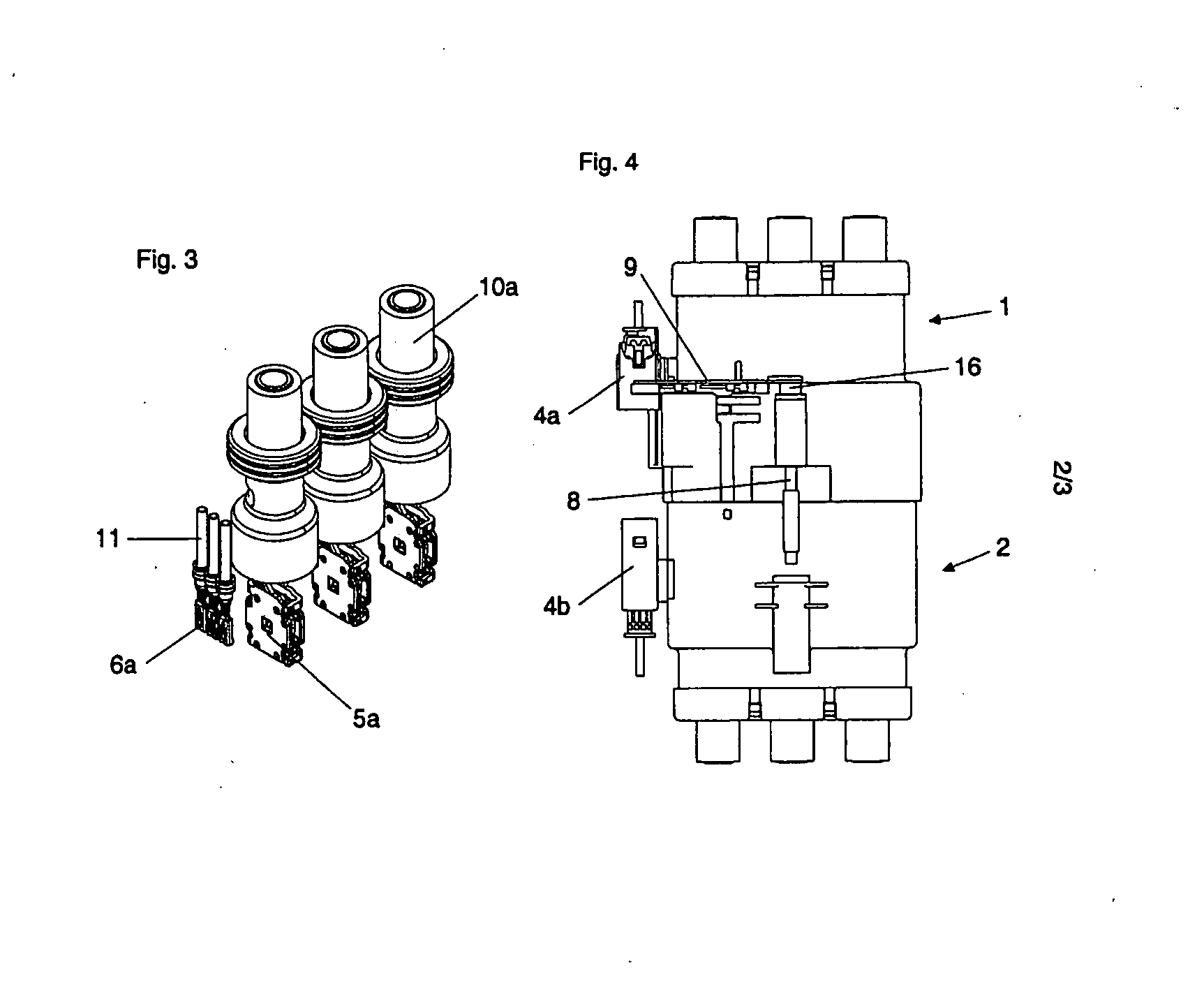
[0027]First connector part 1 includes a high-load (“HL”) housing 3a and a low-load (“LL”) housing 4a. LL housing4a is situated on a side wall of HL housing 3a so as to be vertically movable in the plug-in direction. LL housing 4a is vertically movable in the plug-in direction by a linear guide designed as, for example, a dovetail guide. Electrical HL contacts 5a are in HL housing 3a and electrical LL contacts 6a are in LL housing 4a (see FIG. 3 which shows contacts 5a, 6a without the surrounding housings 3a, 4a).

[0028]Similarly, second connector part 2 includes a HL housing 3b and a...


PUM


Abstract

An electrical connector includes two connector parts each having a high-load (“HL”) housing with an HL contact and a low-load (“LL”) housing with a LL contact. One LL housing is movable relative to the other LL housing. The parts are movable to join and separate from one another. The HL housings join upon the parts joining such that the HL contacts join and establish a HL connection. The LL housings join after the one LL housing moves toward the other LL housing while the parts are joined such that the LL contacts join and establish a LL connection. The LL connection is prevented from being established until the HL connection is established as the LL housings are prevented from joining until the HL housings join. The HL connection is prevented from separating until the LL connection is separated as the HL housings are prevented from separating until the LL housings separate.

Description

CROSS-REFERENCE TO RELATED APPLICATIONS[0001]This application claims foreign priority benefits under 35 U.S.C. § 119(a)-(d) to DE 10 2006 033 323.3, filed Jul. 17, 2006, which is hereby incorporated by reference in its entirety.BACKGROUND OF THE INVENTION[0002]1. Field of the Invention[0003]The present invention relates to an electrical connector for establishing an electrical high-load (“HL”) connection(s) and an electrical low-load (“LL”) connection(s) in which the LL connection cannot be closed until the HL connection is closed and the HL connection cannot be separated until the LL connection is separated.[0004]2. Background Art[0005]DE 10 2004 054 360 A1 (corresponding to U.S. Pat. No. 6,982,393) describes an electrical connector which includes power terminals and attachment-sensitive terminals. Via a lever, the power terminals are connected to one another and then the attachment-sensitive terminals are connected to one another. The attachment-sensitive terminals actuate a relay...

Claims


Application Information

Patent Timeline
Patent Type & Authority Applications(United States)
IPC IPC(8): H01R13/62
CPCH01R27/02
Inventor NATTER, BRANTLEYPLATE, HERBERT
Owner KOSTAL KONTAKT SYST
Why Eureka
Try Eureka