Information clip for flexible tubing

a flexible tubing and information clip technology, applied in the field of flexible tubing, can solve the problems of text size and clarity limitation, and the text applied to the extension tube is susceptible to rubbing off, and achieve the effect of preventing translation

Inactive Publication Date: 2008-02-28
MEDICAL COMPONENTS INC
View PDF49 Cites 57 Cited by
  • Summary
  • Abstract
  • Description
  • Claims
  • Application Information

AI Technical Summary

Benefits of technology

[0011]In another general group of embodiments, the inventive device is particularly adapted to be utilized in conjunction with a clamp member that is secured to and along the flexible tubing. The device is so shaped and dimensioned to at least partially conform to and to be positioned along one or more outer surfaces of the clamp member and includes a connection section that self-secures or clips to portions of the framework of the clamp member and / or a connection section that self-secures or clips to the flexible tubing adjacent to the clamp member, or even within the interior of the clamp member, all in a manner to prevent translation along the tubing away from the clamp member. The device may have one, or two or three indicia-bearing outwardly facing surfaces. With this type of embodiment, the device does not interfere with the operability of the clamp member when it is being activated between clamping and unclamping states with respect to the tubing, and the device further does not impinge on fluid flow through the tubing.

Problems solved by technology

However, one drawback to this approach is that text size and clarity is limited, since the extension tubes are tubular and are typically translucent.
Additionally, the text applied to the extension tubes is susceptible to rubbing off over time.

Method used


Image

  • Information clip for flexible tubing
  • Information clip for flexible tubing
  • Information clip for flexible tubing

Examples


first embodiment

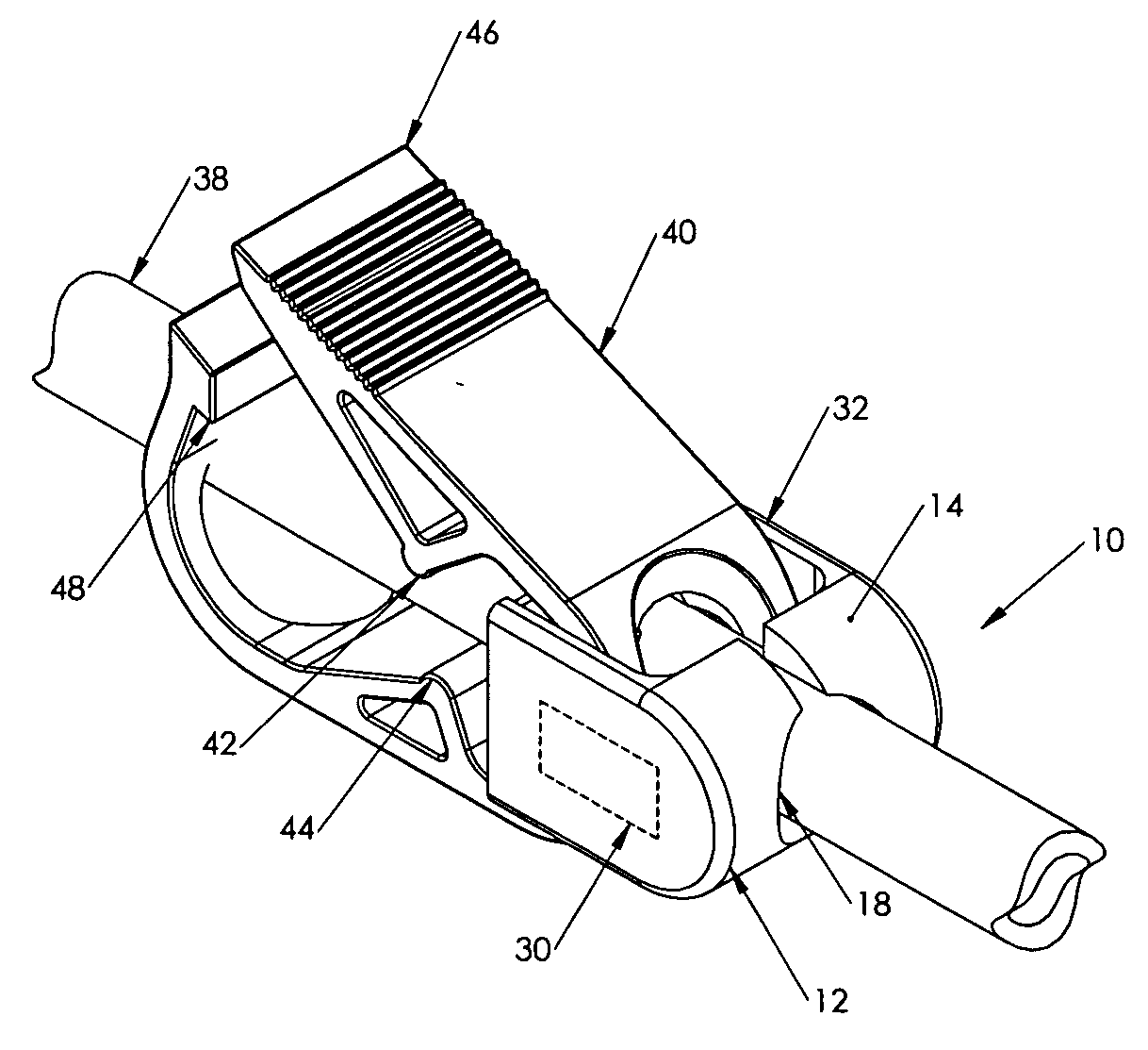
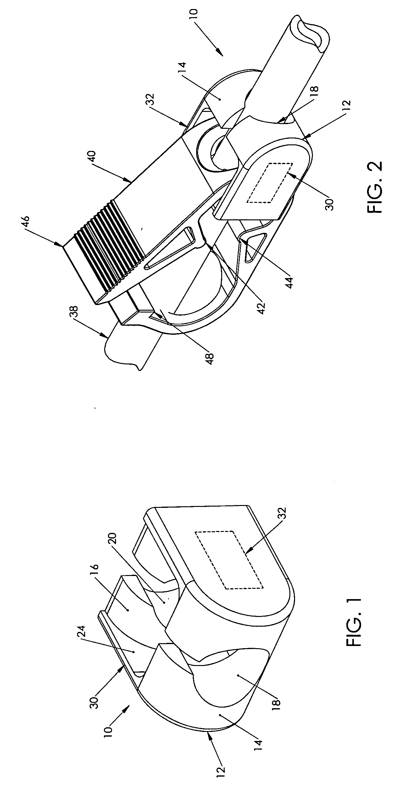
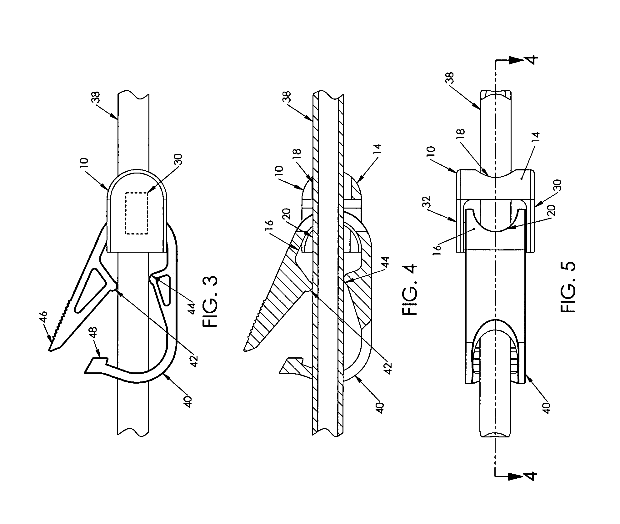
[0037]In the first embodiment shown in FIGS. 1 to 5, an indicia-bearing device 10 includes a body 12 and a pair of side walls 30,32, one on either side of the device and that are joined by the device body 12, each having outwardly facing surfaces that may be indicia-bearing. Also seen in FIGS. 2 to 5 is a length of flexible tubing 38, and a clamp member 40 secured thereto and therealong, the clamp being manipulatable between an unclamping state as shown, and a clamping state (not shown) in which fluid flow through the tubing is occluded. FIGS. 3 and 4 show the sections 42,44 that would impinge on the flexible tubing for its occlusion with the end of the arm 46 latching to the clamp body at latch 48 to hold it in the clamping state; such a clamp is conventionally known as a Roberts clamp.

[0038]Device 10 is provided with first and second transverse connecting sections 14,16 separated by a clearance 24 that each include a C-shaped channel 18,20 extending therethrough both being coalign...

second embodiment

[0039]In FIGS. 6 and 7 is shown indicia-bearing device 50. Body 52 includes a connecting section 54 with a C-shaped channel 58 that is adapted to clip onto the flexible tubing 38 at a location within the clamp 40. Device 50 is shown to have two indicia-bearing surfaces 70,72 with surface 70 eventually being positioned along one side of clamp 40. Surface 72 extends orthogonally from a depending bottom edge 74 of surface 70 to extend transversely under the bottom of clamp 40 and tubing 38 of the tubing / clamp assembly.

third embodiment

[0040]FIGS. 8 and 9 illustrate indicia-bearing device 100 of the present invention. In device 100, body 102 includes a transverse connecting section 104 defining therethrough a C-shaped channel 108 for enabling device 100 to clip onto the flexible tubing 38 at a location within clamp 40. Device 100 provides a first indicia-bearing surface 120 that extends along one side of clamp 40, while a second indicia-bearing surface 122 extends in the opposite direction from, and on the opposite side of the tubing from, first indicia-bearing surface 120 to extend past an adjacent end of clamp 40 and therebeyond, thus not occluding the view of the length of tubing 38 within clamp member 40. Optionally, the inwardly facing surface of first surface 120 may also be provided with indicia that would be viewable through the clamp and the transparent tubing.

[0041]Another embodiment of device 100′ is shown in FIG. 10 that is similar to device 10 of FIG. 1, having a body 102′ that includes a transverse s...


PUM


Abstract

Information-bearing articles (10,50,100,100′,150, . . . 850) for securing to flexible tubing (38) such as catheters and their extension tubes, to provide important information about the tubing (38) such as flow rating or contraindications on types of cleaning fluid not to be used therewith. The devices are provided with large outwardly facing indicia-bearing surfaces (30,32;70,72;120,122; . . . 834) and may be clipped directly to the tubing (38) at a selected location therealong, or be clipped directly to a clamp member (40,330) that is disposed along and around the tubing for clamping the tubing (38) when desired to occlude fluid flow therethrough. Those devices (10,100,100′,550, . . . 750) clippable to the tubing may have a C-shaped channel (18,20,58,108,554,604) therealong that may be flexed open to be placed about the tubing, which may be temporarily compressed as well to enter the channel, or the devices may be rings (800,850) that clip closed about the tubing (38). Other devices (200,250, . . . 500) are adapted to be clipped to the clamp (40,330) by latch projections (208,210;258,260; . . . 508,510). Still others (50,150) may be clipped to the tubing (38) but be adapted to be placed partially around an end or a side of the clamp (40,330).

Description

CROSS-REFERENCE TO RELATED APPLICATIONS[0001]This application claims priority from Provisional U.S. Patent Application Ser. No. 60 / 839,913 filed Aug. 24, 2006.FIELD OF THE INVENTION[0002]This relates to flexible tubing and more particularly to medical tubing such as catheters and their extension tubes and to information-bearing devices therefor.BACKGROUND OF THE INVENTION[0003]Catheters for the introduction or removal of fluids may be located in various venous locations and cavities throughout the body for the introduction or removal of such fluids. Such catheterization may be performed by using a single catheter having multiple lumens. A typical example of a multiple lumen catheter is a dual lumen catheter in which a first lumen introduces fluids and a second lumen removes fluids. These catheters are very useful for procedures such as hemodialysis, wherein blood is removed from a patient through the first lumen for processing in a hemodialysis machine, and the processed blood is re...

Claims


Application Information

Patent Timeline
Patent Type & Authority Applications(United States)
IPC IPC(8): A61M5/00
CPCA61M39/284A61M2205/58A61M2205/583G09F3/205A61M2205/60A61M2205/6063A61M2205/585
Inventor SCHWEIKERT, TIMOTHYCHESNIN, KENNETH J.STEPHENS, JOHNSANFORD, KEVIN
Owner MEDICAL COMPONENTS INC
Why Eureka
Try Eureka