Tip-up fishing device for ice fishing

a technology for ice fishing and fishing equipment, which is applied in the field of ice fishing, can solve the problems of reducing metabolism, reducing food intake, and reducing the strength of the inferrior grade of wood that they were constructed from, and achieves the effects of reducing the risk of injury

Inactive Publication Date: 2008-03-06
RICHARDSON WAYNE FRANCIS
View PDF80 Cites 9 Cited by
  • Summary
  • Abstract
  • Description
  • Claims
  • Application Information

AI Technical Summary

Benefits of technology

[0011]It is another object of the invention to provide an ice fishing system that has a method for applying several types of counterweight systems to adjust to any lure an angler might use and thus retain the balance thereof.
[0012]It is another object of the invention to provide an ice fishing system that has a unique pivot pin that allows the pole to easily be removed from the base, by the angler,
[0013]yet makes it nearly impossible for a fish to pull the pole from the base.
[0014]It is another object of the invention to provide an ice fishing system that provides a place where snow or ice to be placed on the base further securing it, and by being made of a durable material allows the easy removal of snow or ice at the conclusion of fishing without damaging the device.
[0015]It is another object of the invention to provide an ice fishing system that has a place for the pole to rest on when in the quiescent position and which keeps the pole from freezing to the ice.
[0016]In accordance with the present invention, there is provided an ice fishing system having a one piece base made from a cylindrical material and which is bent in a U shape. As it lays parallel with the ice, the two cylindrical legs bend upwardly to a position slightly past vertical to form two masts. In the distal end of these masts there are provided recessed openings. Across the two legs parallel two the ice there is provided a support plate which acts as a place for the rear of the pole to rest in the quiescent position and which also acts as a means of strengthening the base. The pole also is made of a cylindrical material and is one piece and is curved in shape. In the center of the pole is an aperture through which a pivot pin passes and resides. The projecting ends of the pivot pin are then bent downwardly to form two legs. These legs will then reside in the recessed openings arising from the base when the pole is in the quiescent position. This allows the pole to freely rock back and forth between the masts. The pole also has a hole at the end thereof through which the line passes on its way to the hole in the ice. The pole also has a protrusion at a point between its tip end and midpoint, along the center line of the pole, through which there will be a hole. This protrusion acts as a guide for the line and will be the place where an (optional) wind sail will attach. Near the rear portion of the pole along the center line two posts protrude at opposing angles and act as the reel, a place for the line to be stored. A short distance beyond the reel and along the center line, a protrusion is disposed and of a bright colored material, a flag, which acts as a visual aid for the fisherman to determine strikes. This flag also acts as a place where weights can be crimped on to help balance the pole and offset the weight of the lure or bait. At the very rear of the pole, another post is disposed along the center line and acts as a place where weights can be slid on to further help in offsetting the lures weight. These weights will be held in place by an O-ring . . .

Problems solved by technology

This is probably due to their decreased metabolism and subsequent reduced food intake.
Thus the dilemma: a tasty, highly prized game fish in a harsh environment and which, due to their reduced metabolism, are extremely light biting.
I also noticed that the cost saving inferrior grades of wood that they were constructed from did not hold up well in the harsh conditions associated with ice-fishing.
Upon using it I soon realized that it also lacked the needed sensativity and I also found that it took up signigant space even when collapsed.
Once again the wood it was constructed from was a weakness and the reel that was attached to it seemed unnecessary as in that most fish, when hooked, were quickly hand lined to the surface.
The bases of these devices were square and bulky when stored.
The number one problem I observed was that there were no measures built into the devices to offset the weights of the lures and baits used or to bring the pole back into balance.
This was also true when a fish struck and pulled the pole down, it stayed down and thus there was no way to tell if the fish was still on the line.
Quite often I would set the hook and the fish would be gone and this in turn would scare the fish
yet makes it nearly impossible for a fish to pull the pole from the base.

Method used


Image

  • Tip-up fishing device for ice fishing
  • Tip-up fishing device for ice fishing
  • Tip-up fishing device for ice fishing

Examples


Embodiment Construction

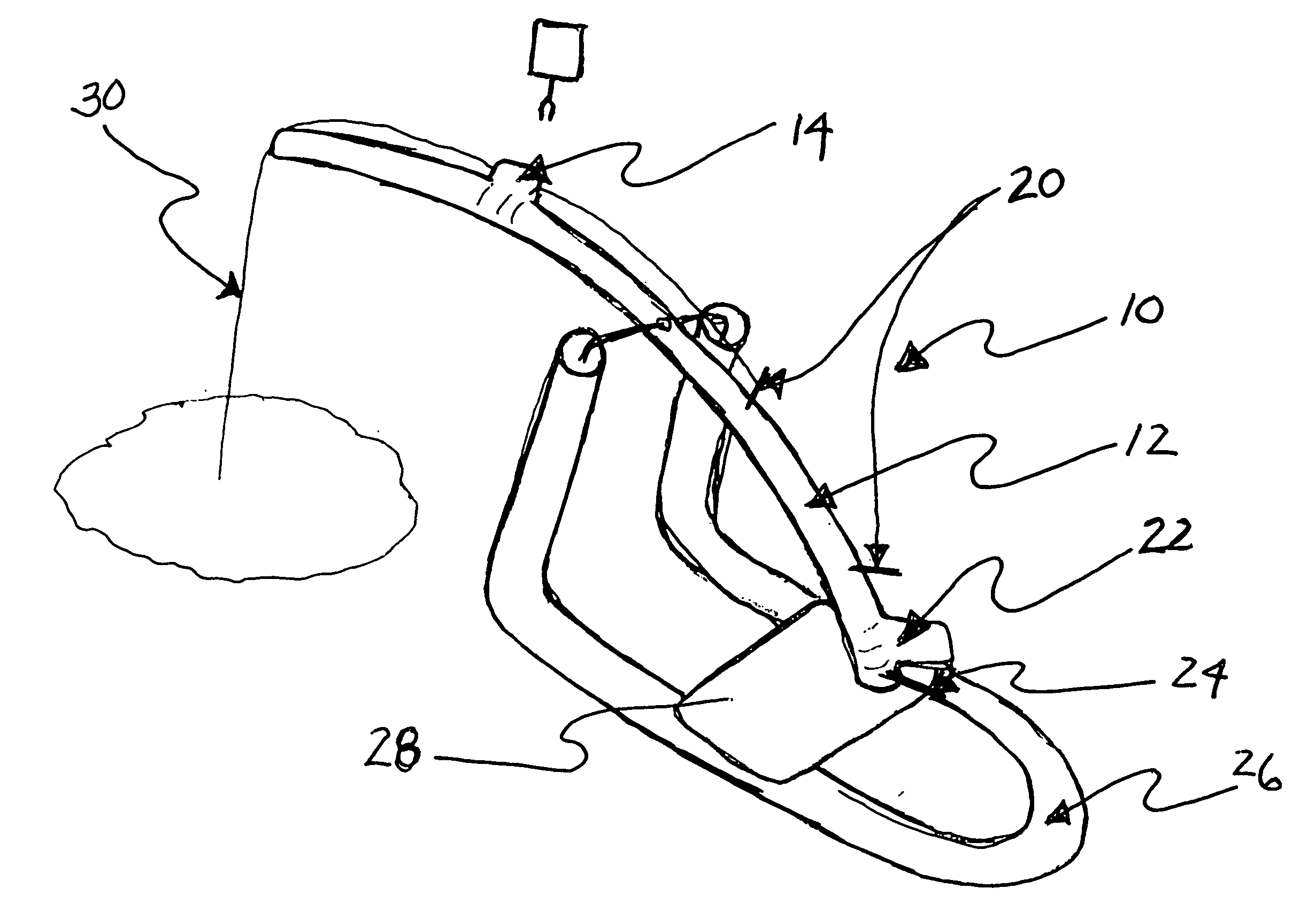
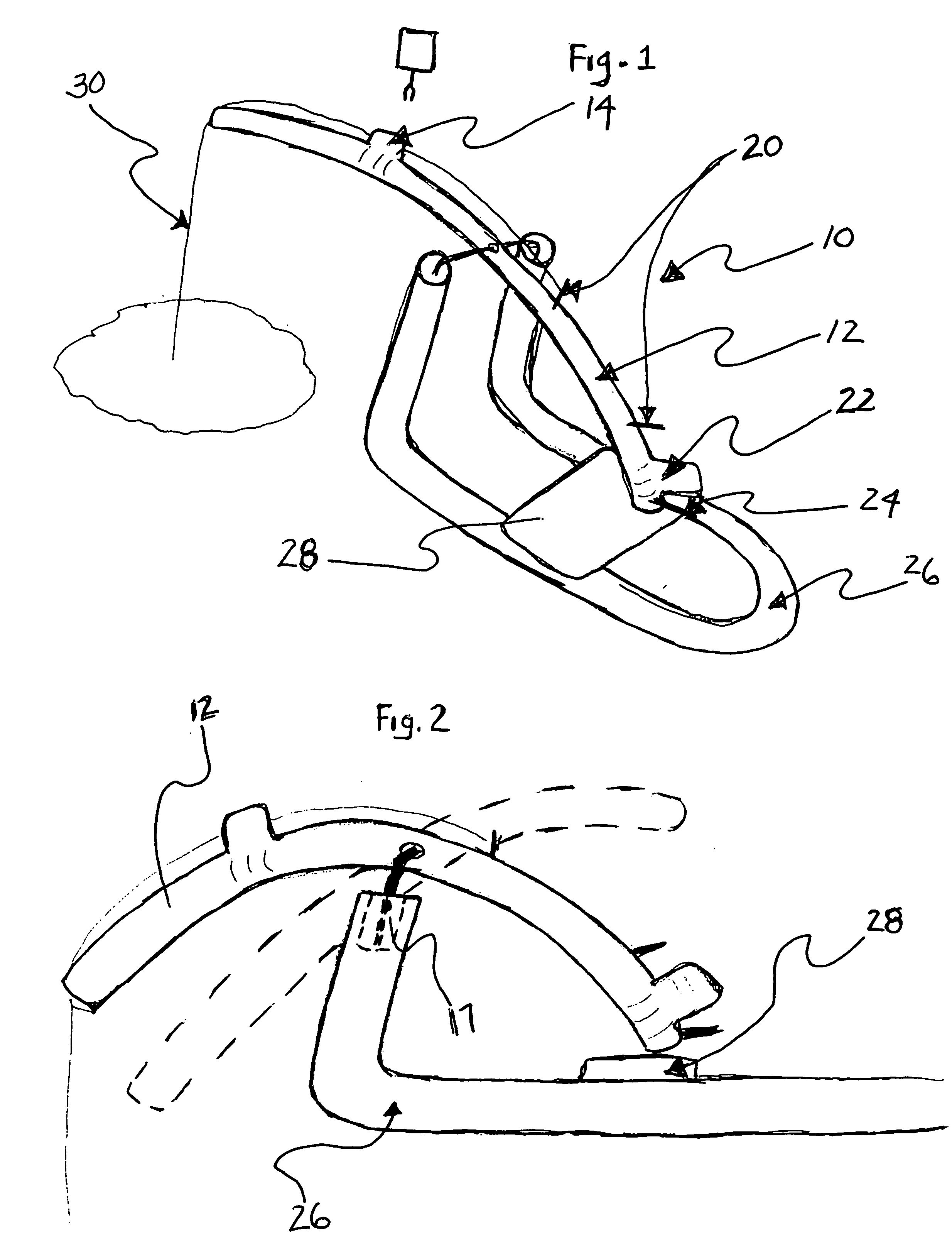
[0027]FIG. 1 is a perspective view of the embodiment of the invention and the new and improved ice fishing system embodying the principles and concepts of the present invention.

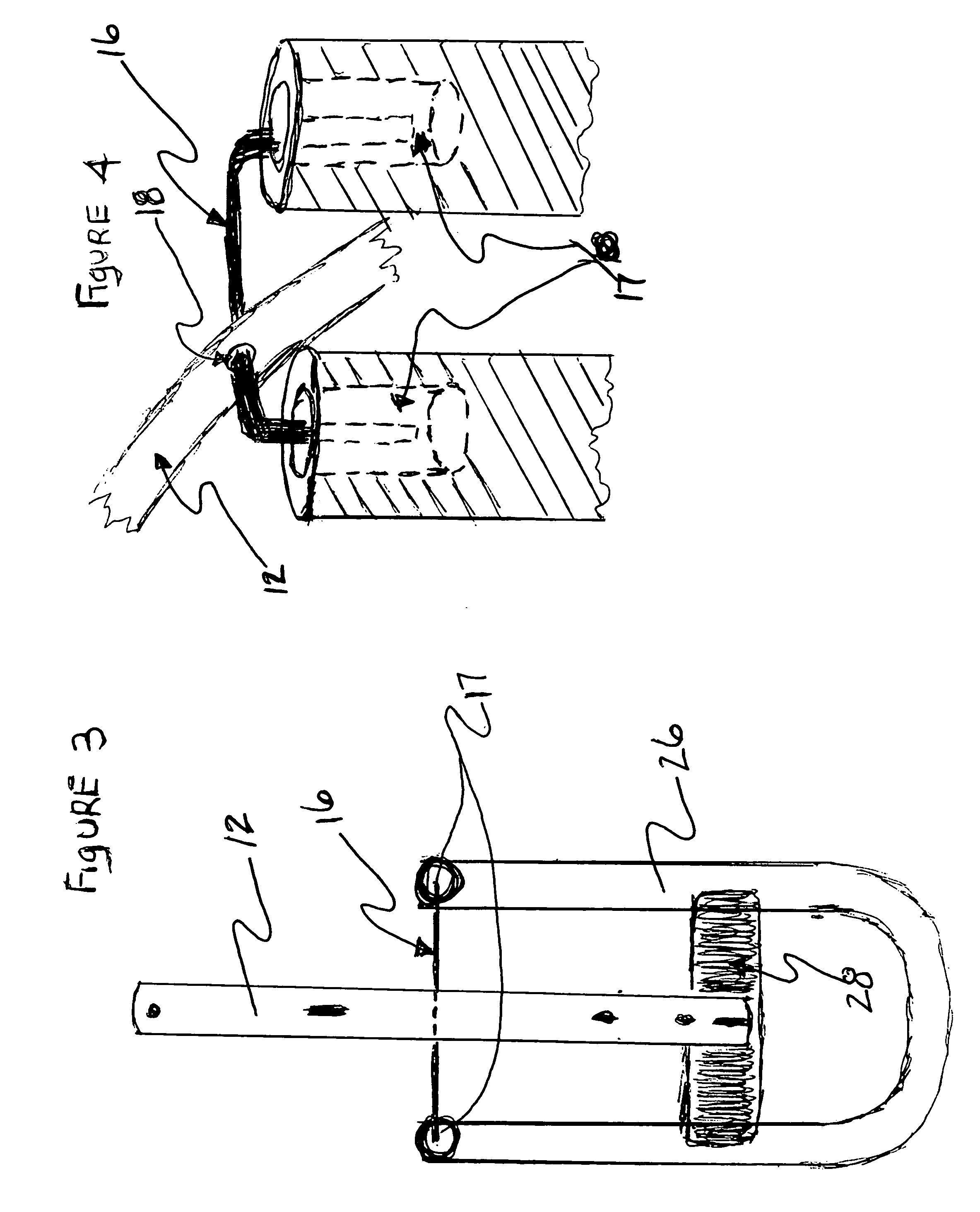
[0028]The present invention, the ice fishing system, is comprised of a plurality of components. The ice fishing system of the present invention comprises of a fishing pole 12 which is bent in a curved shape and is of a cylindrical material. The pole 12 has a tip aperture 34 through which the fishing line 30 passes and depends therefrom as it journeys towards the hole in the ice. Mid way between the tip aperture 34 and the pivot pins the guide 14 which protrudes from the pole 12 and it is through this guide 14 that the line passes as it travels from the reel 20 to the tip aperture 34. This guide 14 also is the place where the (optional) wind sail 36 is attached to the pole 12 when a fisherman chooses to employ it. At the midpoint of the pole 12 a pin aperture 18 will be provided. Through this pin aperture 18 t...


PUM


Abstract

An ice fishing system is provided including a one piece base with two masts arising there from. Also included is a curved fishing pole which is coupled to the base with a U-shaped pin and upon which the pole resides. This U-shaped pin also allows the pole to rock to and fro between the masts and this pole has a fishing line that depends from an end thereof.

Description

FIELD OF THE INVENTION[0001]The present invention relates to ice fishing and, more particularly, to a device designed to detect the slightest strikes from fish. The device is designed to be durable and simple to operate in the harsh environment associated with ice fishing . . .BACKGROUND OF THE INVENTION[0002]Since the beginning of recorded history man has strived to perfect his methods of gathering food, Mankind's earliest inventions came about as a result of his need to keep himself alive. My invention is a further refinement of this art of gathering food and in this case, fish. Humans have continuously striven to improve their techniques for gathering food in the most efficient manner possible. I believe that this invention is a unique tool and is at the pinnacle of simplicity, durability and effectiveness within the scope of today's technology.[0003]The problem my invention solves is the capture of light biting fish in the winter period of the year. The fish that my device targe...

Claims


Application Information

Patent Timeline
Patent Type & Authority Applications(United States)
IPC IPC(8): A01K97/12A01K97/10
CPCA01K97/11A01K97/01
Inventor RICHARDSON, WAYNE FRANCIS
Owner RICHARDSON WAYNE FRANCIS
Why Eureka
Try Eureka