Modular Metal Wall Framing System

a metal wall and modular technology, applied in the direction of walls, constructions, building components, etc., can solve the problems of slow adoption of innovative methodologies or technologies in the construction industry, and achieve the effect of reducing the number of unskilled labor and being convenient to us

Inactive Publication Date: 2008-03-06
ROSENBERG ZEV
View PDF39 Cites 18 Cited by
  • Summary
  • Abstract
  • Description
  • Claims
  • Application Information

AI Technical Summary

Benefits of technology

[0068]The invention also provides a modular metal framing system that can include an optional side spacer or bracer that provides spacing and alignment of studs and serves as a larger surface for supporting drywall and into which metal screws can be more conveniently secured to hold the drywall to the frame.
[0069]The present invention is directed to a modular metal framing system for constructing wall frames in virtually any type of building construction. The system is complete insofar as it requires virtually no additional hardware and can be readily used by unskilled labor. Metal wall frames constructed in accordance with the invention can be completed in a fraction of the time and at much lower cost than wood frames as well as other conventional metal frame systems.
[0070]In accordance with the invention, upper and lower metal channels are formed with a series of evenly-spaced locators or stops that accurately locate a series of metal studs along the channels. The channels also include retainers or prongs located adjacent to the locators or stops for fitting within slots formed in the studs. The channels further include scored or notched areas located adjacent to the stops and prongs for allowing a portion of each channel side wall to be crimped inwardly to hold a stud in place on the channel, or flexible clips that hold the stud in place along the channel.

Problems solved by technology

The construction industry, whose workers are tradition- and trade-oriented, has been very slow to adopt any innovative methodologies or technologies.

Method used


Image

  • Modular Metal Wall Framing System
  • Modular Metal Wall Framing System
  • Modular Metal Wall Framing System

Examples


Embodiment Construction

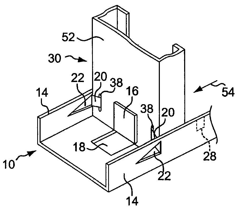
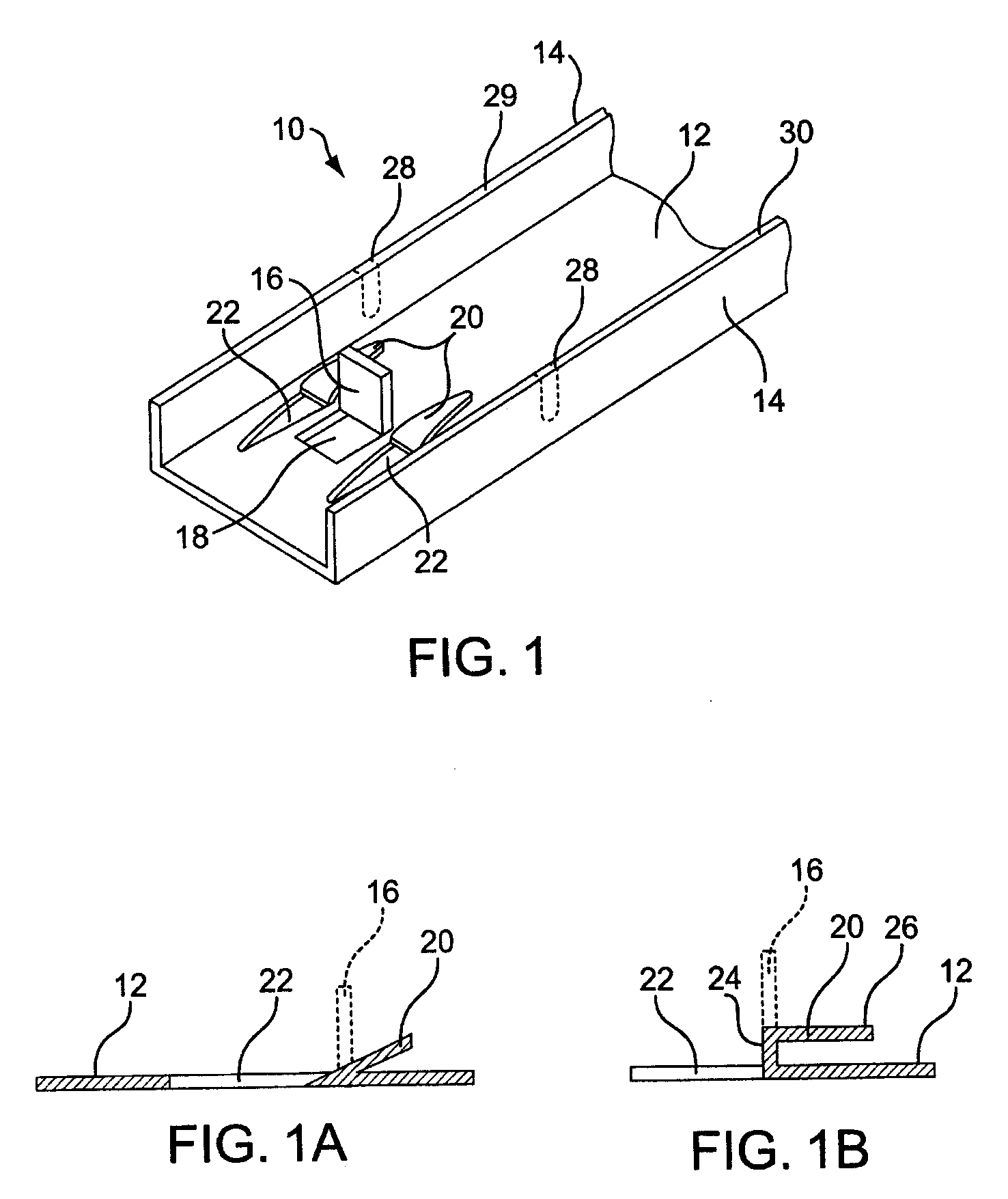
[0126]The present invention will now be described in conjunction with the drawings, beginning with FIG. 1, which shows a channel member 10 constructed in accordance with the invention. The channel member 10 is adapted to be installed in a known manner on a lower support surface such as a floor. An identical second or upper channel member 10 is typically installed in a known manner on an overhead support surface such as a ceiling. The upper and lower channel members are aligned parallel with one another and typically aligned within a common vertical plane.

[0127]The channel member 10 includes a flat, longitudinally-extending central floor 12 and a pair of upstanding parallel side walls 14 that are bent upwardly at right angles from each side of the floor 12. The channel member 10 is formed of a sheet metal material such as steel. A stud locator or stop member in the form of a tab 16 is struck or punched upwardly from the channel floor 12, leaving behind an open aperture 18 in the floo...


PUM


Abstract

A metal stud assembly includes a stud used in constructing a metal wall frame between two channel members, and an extender longitudinally slidably mounted within the stud. The stud includes a central column portion, two side walls formed on opposite sides of the central column portion, a retainer, at least one alignment slot formed in the stud for receiving the retainer formed on one of the channel members, and an indented portion formed in at least one of the side walls for receiving a spacer bar. The alignment slot is formed in at least one end portion of the central column portion. The extender includes an upper portion having side walls parallel to the side walls of the stud, and a lower portion having side walls that join the upper portion side walls at a top end and which taper at a bottom end to fit within the stud.

Description

CROSS-REFERENCE TO RELATED APPLICATION[0001]This is related to, and claims the benefit under 35 USC §119(e) of U.S. Provisional Application for Patent No. 60 / 824,652, which was filed on Sep. 6, 2006.FIELD OF THE INVENTION[0002]The present invention relates in general to metal wall frames, and in particular to such frames which include channels and studs having integrally formed connectors, locators, and retainers.BACKGROUND OF THE INVENTION[0003]Framing systems have been developed using metal channels and studs in place of more conventional wood frames. Such systems have been adapted to construct various structures including residential and commercial buildings, and particularly the partitions of such buildings. Although these systems function adequately, they are sometimes difficult to use and can take longer to assemble than can conventional wood frames.[0004]Because of these drawbacks, many builders have been reluctant to adopt conventional metal framing systems. Moreover, instal...

Claims


Application Information

Patent Timeline
Patent Type & Authority Applications(United States)
IPC IPC(8): E04C3/32
CPCE04B2/7457E04B2/767E04B2/762
Inventor ROSENBERG, ZEV
Owner ROSENBERG ZEV
Why Eureka
Try Eureka